The main drive brake, motor control and indexed stop reference is a small part of a larger run activity sequence, but it can influence overshoot, inconsistent stopping, delayed restart, brake drag or an index that settles away from its reference. A reliable diagnosis should begin with repeatable unit data rather than a replacement guess. This guide gives maintenance teams a structured way to isolate the finding while preserving the delivered unit references.
A practical paper cup machine main drive brake troubleshooting review should connect the visible symptom with the command, physical response and finished output. Final limits, parts and adjustments remain configuration-specific; use the configuration electrical and drive drawings, brake documentation and unit stopping work instruction instead of applying a universal value.
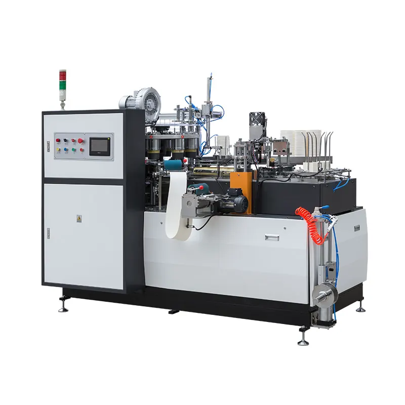
Establish a reproducible inspection finding
Capture motor and brake model, drive output, brake rectifier or relay, home sensor, encoder and mechanical transmission. Mark when the concern appears during normal stop, emergency stop test under controlled conditions, warm restart and low-speed positioning. Include the operator observation, unit state, consumable or job identity and the last known acceptable run activity period. This prevents several different faults from being grouped under one general alarm or quality description.
Keep samples or videos in sequence and label the unit position, direction and time. A pattern tied to one station, one direction, one speed transition or one consumable lot is more useful than a mixed collection of rejected output. Review the relevant context in the VFD and motor drive troubleshooting guide before changing a setting.
Compare stop behavior under controlled states
| Observed finding | Data to collect | Diagnostic direction |
|---|---|---|
| Stop position varies in one direction | Encoder trace, home signal and commanded deceleration | Reference signal, drive tuning or backlash |
| Brake releases late at startup | Command timing, coil voltage and motor current | Control delay, rectifier or mechanical release |
| Motor runs hot with stable run activity | Current trend, brake air gap where applicable and sound | Brake drag, overload or alignment |
| Overshoot grows after warm-up | Cold and warm stop distance, cycle rate and brake temperature | Thermal change, friction or drive behavior |
| A hard stop follows power removal | Stopping sequence and stored-energy assessment | Incorrect control sequence or brake engagement |
Control hazardous energy and preserve references
Apply the site lockout and isolation work instruction for electrical, pneumatic, vacuum, thermal, gravity and stored mechanical energy that applies to this equipment. Verify the zero-energy state before guards, terminals, tubing, tooling or drive components are accessed. Hot surfaces and charged electrical parts may remain hazardous after the unit stops.
Photograph connectors, tube routing, witness marks, adjustment positions, wiring labels and module orientation before disassembly. Qualified personnel should perform live electrical or pressure data values only when the controlled diagnostic work instruction specifically requires them and appropriate controls are in place.
Inspect the module in its complete load path
Separate electrical brake command from mechanical braking force and drive-controlled deceleration. Include coupling, gearbox, chain or belt transmission, encoder mounting, home sensor and indexed load in the data path.
Clean only by the authorized method and preserve deposits, wear bands, damaged parts or filter debris when they may explain the event. Replacement parts must match the configuration identification and service requirements. A visually similar module can have different electrical, pneumatic, thermal, dimensional or consumable characteristics.
Compare command, response and finished output
Place the command data beside the physical response: controller output, valve or drive state, sensor transition, pressure or temperature behavior, motion and final finished item. The sequence shows whether the module failed to receive a command, received it but did not respond, or responded correctly while another process variable created the defect.
Use calibrated or verified instruments appropriate to the configuration work instruction. Capture measurement location, instrument resolution, unit state and repeated results. Avoid converting a single observation into a tolerance; acceptance criteria must come from controlled drawings, manuals, consumable data or an agreed known-good baseline.
Rule out interacting unit and consumable causes
Verify upstream preparation and downstream handling before closing the diagnosis. Consumable identity, contamination, alignment, lubrication, air or electrical supply, timing, load and recent maintenance can change how the module behaves. The rotary encoder and home-position guide provides a related system verify that can prevent a local repair from masking the original source.
Change one controlled variable at a time and log the before-and-after effect. If several adjustments are made together, a short improvement cannot be attributed to one cause, and the fault may return when speed, temperature, roll diameter or run activity demand changes.
Choose corrective work from authorized data
Classify the finding as contamination, connection, wear, misalignment, supply, control, consumable or configuration. Then match the corrective action to the module documentation and the unit supplier’s guidance. Do not bypass an interlock, increase a setpoint beyond its controlled range or modify a safety-related circuit to keep run activity running.
Where the data is incomplete, preserve the unit state and send a compact data pack for review. It should contain unit and module identity, annotated photos, a sequence video, readings with locations, alarms, consumable or job data, recent service history and representative good and bad output.
Verify the repair in stages
Before power or pressure is restored, check tools are removed, connections are secure, guards are reinstated and the work area is clear. Use the authorized manual, jog or slow-cycle verify first, then progress through small controlled run activity stages while watching the original symptom and any secondary effect.
Use the controlled sequence to repeat stops from defined positions and speeds, capture final reference error, restart behavior, current and sound, then check tooling clearance before producing labeled cups. Do not release the unit based only on one acceptable cycle. Document the parts or recipe values changed, final observations, retained samples and the person authorized to return the equipment to run activity.
Prevent recurrence with a traceable maintenance capture
Add the confirmed inspection point to the maintenance plan with an objective method and a reference source. Trend the finding by time, cycles or run activity demand as appropriate, but do not invent a replacement interval. Module finding, environment, consumable and unit loading should determine the review frequency.
Link the maintenance capture to alarms, run activity samples and spare-part identity. This makes future troubleshooting faster and helps purchasing teams order the correct configuration instead of a visually similar substitute.
Frequently asked questions
Can brake torque be adjusted by trial and error?
No. Brake service and air-gap or torque recipe values must follow the exact module documentation and safety work instruction.
Does an accurate home sensor eliminate mechanical backlash?
No. A correct signal can coexist with transmission clearance or movement between the sensor reference and tooling.
Should an emergency stop be used as a routine positioning method?
No. Functional stopping and emergency stopping have different purposes and must follow the unit safety design.
What data helps the supplier separate drive and brake faults?
Provide stop videos, drive status, command timing, encoder or home signals, warm and cold behavior, current and transmission observations.
Send the unit model, module identity, labeled samples, sequence video, data values and service history through our inquiry page. HANNAI can review the data against the configuration unit configuration.