A roll die cutter air shaft leak can reduce grip between the shaft and reel core, allowing slip that resembles a web-tension fault. Before changing brake settings, check whether the winding or unwinding shaft retains its specified inflation and transmits the required torque without movement at the core interface.
This guide applies only to shafts or chucks that use pneumatic expansion. Mechanical and differential shafts require their own procedures. Confirm shaft model, core dimensions, reel mass and operating limits with the equipment supplier; no common inflation pressure covers every design.
Diagnostic decision table
| Symptom | Possible cause | Evidence |
|---|---|---|
| Inflation drops while stationary | Valve, seal or bladder leakage | Pressure retention using the specified test |
| Pressure retained but core slips | Core damage or unsuitable grip | Core bore and gripping-element condition |
| Slip mainly during acceleration | Torque demand or setup mismatch | Reel data and controlled ramp record |
| Uneven expansion | Damaged leaf, lug or bladder assembly | Unloaded inspection after safe removal |
Secure the reel before touching the air system
Stop the line and support the reel with the rated handling equipment. Follow the shaft procedure for unloading and pressure release. A loss of grip can let a heavy reel move; do not use hand restraint or loosen supports while the reel depends on the shaft for retention.
Record core size, reel width, mass and unwind orientation before removal. Photograph the original position and any relative movement marks. These details help distinguish a gripping fault from an incorrect reel or an installation outside the shaft’s approved application.
Measure retention at the defined condition
Identify the inflation valve and specified pressure-checking method. Record initial pressure, elapsed time and the test condition, including whether the shaft is inside an approved core or fixture. Connecting an instrument can itself release a small quantity of air; account for the method when interpreting a change.
Maxcess describes correct inflation and maintenance as important for torque transfer in pneumatic shafts. A monitoring indication is therefore useful evidence, but it is not a replacement for checking the physical core interface. Keep the measurement record with the shaft identification.
Locate leakage without damaging the assembly
Inspect the external valve and accessible connections using the approved leak-detection method. Do not immerse a shaft or apply chemicals without checking compatibility. If an internal bladder is suspected, follow the manufacturer’s disassembly sequence after the reel is removed and energy released.
Inspect gripping elements, retaining parts and the bladder channel for wear or sharp damage that could cause another leak. Replacement bladder dimensions and end connections must match the shaft. A generic tube that fits inside the body is not evidence of correct expansion or retention.
Check core quality and transmitted load
Examine the reel core for ovality, crushing, contamination and evidence of slip. Compare core dimensions with the shaft specification. Uneven or damaged cores can lose grip despite normal pressure. Also inspect shaft leaves or lugs for free movement and consistent contact.
Review acceleration, reel inertia and braking demand within the approved machine envelope. Do not compensate for a slipping core by exceeding inflation pressure. Keep web-tension changes separate from the shaft repair so the effect of each correction can be evaluated.
Validate grip during a controlled restart
After reassembly, verify inflation retention and unloaded function as directed by the shaft maker. Load an approved reel, restore guards and begin the specified startup sequence. Observe from a safe location for relative core movement, unstable tension and abnormal reel motion.
Repeat the relevant acceleration and deceleration condition without exceeding approved loads. Record pressure, reel identity, ramp setting and resulting web behavior. Send HANNAI the shaft label, core measurements and before/after evidence if slip persists; the remaining cause may lie in core quality or drive demand rather than another bladder leak.
Related equipment and next checks
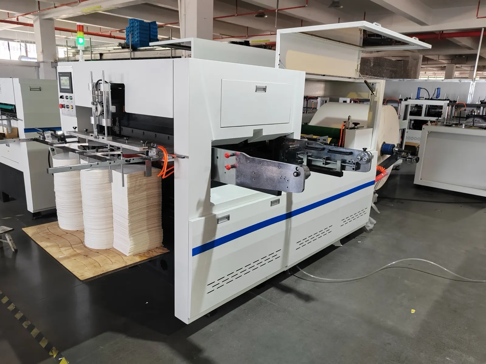
Review the roll die cutting equipment and the related guide to reel loading and unwinding preparation. The Engineering Notes archive connects these checks with wider machine planning.
Technical reference
- Maxcess pneumatic shaft pressure monitoring — general reference; confirm applicability to the installed equipment.
Frequently asked questions
Can more air pressure fix every slipping core?
No. Stay within shaft limits and inspect core compatibility and load.
Are all expanding shafts pneumatic?
No. Identify the actual shaft design before applying this guide.
Does stable pressure prove good grip?
No. Core condition and gripping-element contact also matter.
When should the bladder be inspected?
After safe unloading and according to the shaft service procedure.
Review the evidence with HANNAI
Send your machine model, component identification and the observations described in this guide. Include the drawing or material reference and any before-and-after measurements so the required next check can be identified.