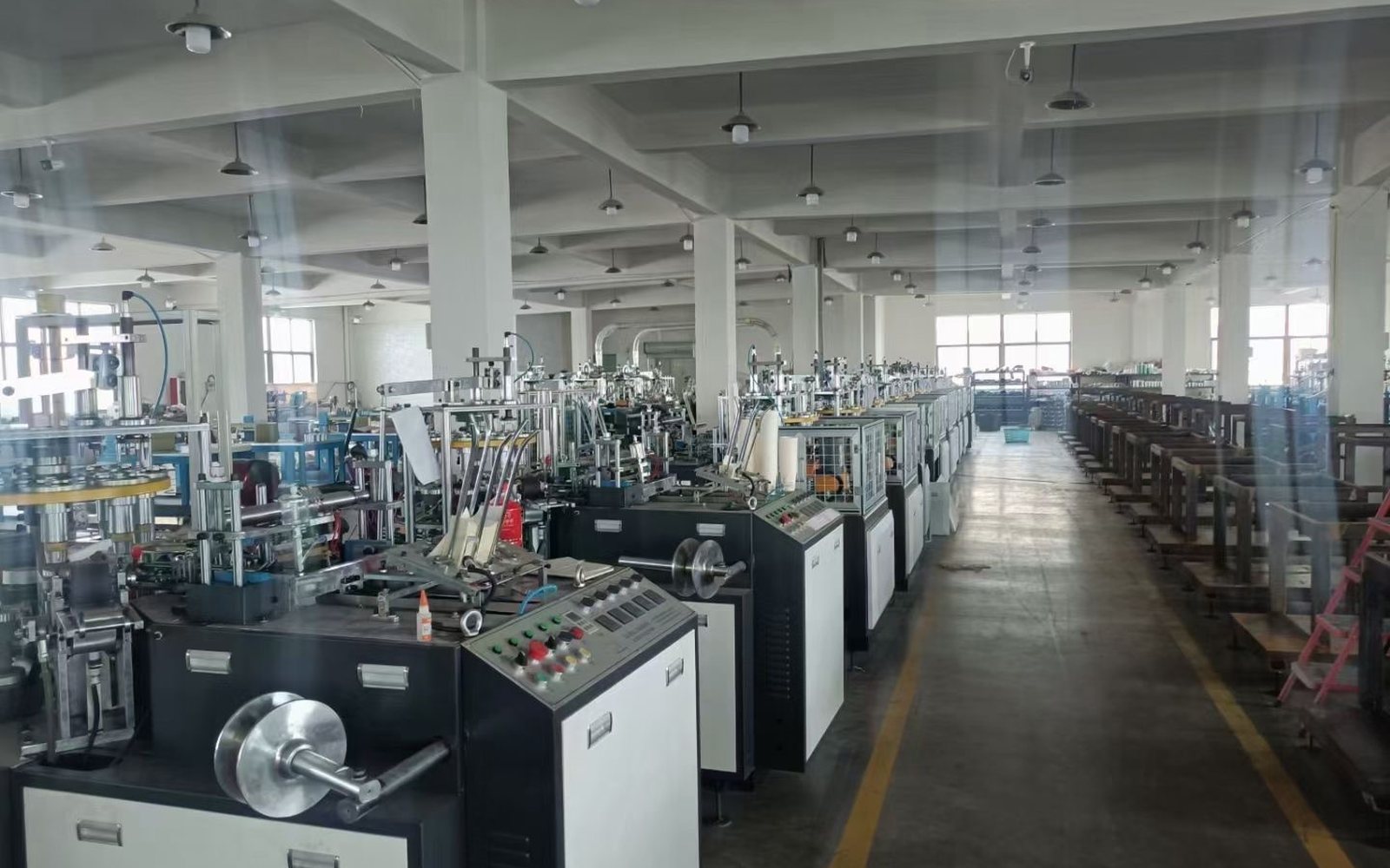
A paper cup machine factory layout should make the production process usable, not simply fit machines into a drawing. Feeding, inspection, collection, packing and maintenance each require access. An arrangement that accommodates the equipment footprint can still create blocked routes or unnecessary handling during production.
Develop the layout around the process you intend to operate. A factory buying printed cup fans needs a different upstream area from one printing and die cutting in house. Keep optional future processes visible without treating them as installed equipment.
Map the material flow before positioning machines
Draw the route from incoming paper and cup fans through forming, inspection, collection and packing to released finished goods. Identify where material is checked, where rejects are held and where production may wait for the next process.
Distinguish approved material from material awaiting inspection. Avoid a route that sends incoming stock through finished-product handling areas merely because it is the shortest path on paper. The production-line planning guide helps define the processes included in your starting scope.
Separate footprint from working space
Obtain the supplier's arrangement and access requirements for the supplied configuration. Include doors, covers, feeding positions, tooling access and maintenance tasks. The operator standing area and material trolley position should remain usable while required access panels are open.
Do not publish one universal clearance for every machine. The correct arrangement depends on the equipment, service access and local requirements. Ask the supplier to identify the applicable dimensions and have the site team confirm the proposed layout.
| Layout area | Question to resolve | Drawing evidence |
|---|---|---|
| Material receipt | Where are lots checked and identified? | Receiving and hold locations |
| Machine feeding | Can stock arrive without blocking operation? | Feeding side and replenishment route |
| Service access | Can required components be reached? | Supplier access zones and panel movement |
| Utilities | Where are connections and isolation points? | Electrical and air interface locations |
| Inspection and packing | Where do accepted cups move next? | Workstations, buffers and handling route |
| Finished goods | How are released lots separated? | Storage and dispatch route |
Plan utilities at the point of use
Record the proposed electrical and compressed-air routes with their connection points. Keep service access, isolation and protection under qualified local design and supplier requirements. Avoid assuming a connection will be convenient simply because a utility exists elsewhere in the building.
Confirm the voltage and electrical requirements and compressed-air requirements for the selected configuration. Simultaneous operation of several machines should be assessed as part of the site utility plan.
Make inspection, rejects and buffers visible
Place quality checks where operators can identify the production interval and prevent rejected cups from returning to accepted output. Provide distinct locations for accepted cups awaiting packing, held production and scrap. Status identification is essential when the same cup design occupies several locations.
A buffer is useful only when its quantity, handling and status are controlled. It cannot permanently compensate for packing capacity below forming output. Define who replenishes material and who clears finished stacks so the layout does not depend on an operator leaving essential tasks unattended.
Walk through routine and exceptional tasks
Review the drawing using a complete shift: stock delivery, replenishment, sample inspection, tooling change, cleaning and dispatch. Then review a jam, maintenance intervention and unloading of replacement equipment. Check that required routes remain usable during those activities.
Confirm lifting and positioning arrangements from supplier instructions before delivery. Floor suitability, local safety requirements and emergency routes belong to qualified site assessment. Treat the layout as a coordination document, not approval of those technical conditions.
Review expansion without creating current inefficiency
Mark likely future equipment and the utility interfaces it would need. Check whether the future process would reverse material flow or require moving the installed machine. Separate reserved space from current work areas so expansion planning does not obscure today's operational responsibilities.
Discuss the dimensions and service needs of the HANNAI equipment range before finalizing the factory plan. Record the drawing revision used for the equipment proposal and revisit it whenever the scope changes.
Review one replenishment and one service task on the drawing
Try a specific walkthrough before approving the arrangement: a trolley brings new cup fans while accepted cups are waiting for packing. Mark the trolley position, operator position and accepted/held stock locations. Check whether the path remains usable without mixing status or obstructing the supplier’s required access zones.
Then examine a documented service task. Show the relevant panel or door in its required open position, where removed parts and tools will be placed, and how the authorized work area is controlled. A drawing that fits all closed machine outlines may fail this review. Correct the arrangement from supplier dimensions and qualified site requirements rather than inventing a clearance around a screenshot.
Use a controlled buffer plan: identify the product, permitted quantity, status and action when its limit is reached. More floor space for stacks does not remove a continuing packing imbalance. Keep the capacity and material-flow decisions connected to the layout revision so a later equipment addition does not invalidate earlier access assumptions.
Frequently asked questions
Is the machine's footprint enough for factory planning?
No. Operation, material handling, inspection, maintenance and local access requirements need additional consideration.
Must a small factory include printing and die cutting?
No. Define whether those processes are outsourced or installed. The layout should reflect the agreed production scope.
Can a larger buffer solve a slow packing process?
It can absorb temporary differences, but continued output imbalance requires a capacity or scheduling solution.
When should the supplier review the layout?
Before the equipment and site interfaces are finalized, and again after a material change to the configuration or location.
Share your proposed layout
Send the usable floor plan, access route, utilities and planned equipment scope through the HANNAI inquiry page. Identify existing constraints and future expansion separately.