Paper cup machine servo system synchronization troubleshooting should connect the motion command, drive status, position feedback, mechanical transmission and observed cup-forming sequence. Where servo-controlled axes are fitted, a fault that appears to be “out of timing” may originate in the reference sequence, feedback path, parameter set, load condition or the driven mechanism rather than in the motor alone.
Confirm what is servo controlled on the delivered machine
Do not begin with an assumed axis count or a generic online parameter list. Identify the supplied drive, motor, feedback device, controller, axis name, mechanical load and master or follower relationship for the actual configuration. Some movements may be servo controlled, while others may use a conventional motor, cam, chain, pneumatic device or another mechanism.
Create a controlled axis map showing what each fitted axis moves, which reference it follows, which sensors permit motion and which machine event should occur before and after it. The machine manual, electrical drawing, drive labels and approved software or parameter backup are the primary references.
Use a synchronization fault evidence table
| Check point | Evidence to capture | Decision question |
|---|---|---|
| Fault identity | Exact drive or HMI alarm, axis name, time and operating mode | Which device first reported an abnormal condition? |
| Command | Commanded position, speed or motion state from the approved diagnostic view | Was the controller requesting the intended movement? |
| Feedback | Actual position or status, following-error trend and reference state where available | Did feedback follow the command consistently? |
| Sequence | Previous and next machine events, sensor states and cycle location | Was motion blocked by a valid process condition? |
| Mechanical load | Coupling, belt, shaft, bearing, cam or driven station condition | Can the mechanism move through its approved path without abnormal load? |
| Configuration | Parameter backup, program revision, replacement history and recent changes | Does the installed configuration match the controlled reference? |
| Recovery proof | Low-risk test result, repeated cycles, cup samples and approver | Was synchronization and product quality demonstrated before release? |
Preserve the first alarm before resetting the system
Record the exact alarm text or code, axis identity, machine speed, cup format, operating mode and last completed machine event. Note whether the fault occurred during power-up, homing, acceleration, steady production, deceleration, manual jog, a stop-and-restart or a format change. A short video of the HMI and mechanism from outside the guarded area can preserve sequence evidence.
Secondary alarms may appear after the first axis stops, so the complete order matters. The remote troubleshooting evidence checklist can organize alarm history, photos and configuration records before supplier review.
Separate motion command, feedback and mechanical result
A professional diagnosis asks three different questions. Did the controller command the movement? Did the drive and feedback system report that the movement occurred? Did the driven mechanism physically reach the correct process position? These answers can differ.
If no command was issued, review the sequence, interlocks and upstream conditions rather than changing the drive. If command and feedback differ, qualified personnel can investigate the drive, feedback connection and approved motion diagnostics. If command and feedback agree but the process position is wrong, inspect the coupling, key, belt, shaft, backlash, slip or mechanical reference under safe isolation. The chain, cam and drive timing guide provides the companion mechanical review.
Review homing and reference establishment
Where the fitted motion system requires homing or an origin search, confirm the approved startup order, reference sensor condition, travel direction, mechanical clearance and completed-reference indication. A shifted reference sensor, interrupted homing cycle or incorrect restored position can create a repeatable offset even when the drive itself is healthy.
Never move a reference device casually to make the alarm disappear. Mark and document any authorized adjustment, retain the original position and prove that adjacent stations remain coordinated. The sensor and interlock troubleshooting guide helps distinguish a missing reference input from a motion fault.
Inspect feedback, power and connections safely
Intermittent synchronization problems can involve loose connectors, damaged feedback cables, poor shielding or grounding, contamination, heat, repeated cable flexing or an unstable power connection. Inspection and measurement inside an electrical cabinet must be performed only by qualified personnel under the site’s electrical-safety procedure.
Do not unplug feedback devices, disconnect motors or perform insulation testing without confirming the drive manufacturer’s approved method. Stored electrical energy and unexpected motor movement remain hazards after a stop. The electrical control cabinet inspection guide explains the wider evidence and isolation boundary.
Check the driven mechanism before tuning parameters
A tight bearing, contaminated slide, displaced guide, damaged transmission component or product jam can increase load and following error. Under approved lockout, inspect the driven path, lubrication condition, fasteners, coupling marks and evidence of contact or slip. Compare with a controlled mechanical reference rather than forcing movement.
Do not use higher torque, wider error limits or more aggressive tuning to conceal mechanical resistance. A parameter change may postpone the alarm while increasing wear or collision risk. Correct the verified physical cause first, then assess whether a controlled motion review is still required.
Control parameters, software and replacement history
Preserve a dated backup before any authorized change. Record the drive model, firmware where relevant, parameter set, controller program revision and replacement component identity. Never copy parameters from another axis or machine only because the hardware appears similar; motor data, feedback type, travel, gearing, limits and motion relationships may differ.
Changes should follow approval, comparison and rollback rules. Link them to the production change control guide so the next shift can distinguish a known configuration from an undocumented adjustment.
Prove recovery through a staged production release
After the verified correction, restore guards and connectors, remove tools and follow the approved restart sequence. Use the permitted manual, reference or reduced-risk check before automatic cycling. Observe repeated motion at the authorized stages before returning to the normal production condition.
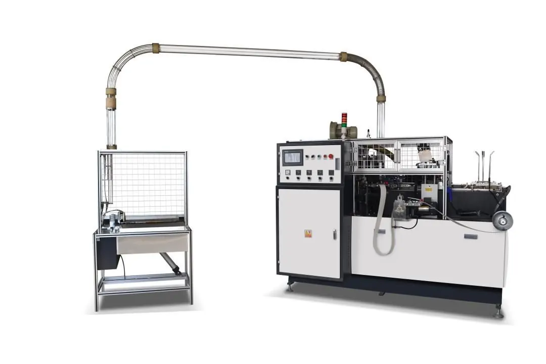
Synchronization recovery is not complete until adjacent feeding, forming, sealing and transfer events remain stable and the cups meet the approved inspection plan. For a servo-controlled configuration such as the HN-SF160 high-speed paper cup machine, the actual motion architecture and acceptance method remain dependent on the delivered configuration.
Frequently asked questions
Does a servo alarm prove that the servo motor has failed?
No. The first alarm can be associated with power, feedback, command, reference, wiring, excessive mechanical load, sequence logic or the drive itself. Preserve the evidence and test the documented fault chain before replacing a component.
Can parameters be copied from another apparently identical axis?
Not without controlled engineering confirmation. Motor data, feedback, gearing, travel limits, direction and master-follower relationships can differ even when two drive labels look similar.
Why can a synchronization fault appear only after speed increases?
Acceleration, load, vibration, cable movement, feedback stability and the available timing margin can change with operating state. Compare command, feedback, mechanism and process evidence at each approved test stage.
When should the machine supplier or motion specialist be involved?
Escalate before changing protected parameters, software, homing logic, electronic gearing, limits or drive hardware, and whenever the factory cannot prove a safe mechanical and electrical condition from the supplied documentation.
Send the machine model, delivered configuration, exact alarm sequence, axis or station identity, HMI and drive photos, event video, recent maintenance and current cup specification through our inquiry page. HANNAI can review the available evidence and discuss the next controlled diagnostic step.