Paper cup machine electrical grounding and signal interference problems can appear as intermittent sensor changes, communication loss, drive trips, unstable analogue values or faults that occur only when a motor, heater or other load switches. These symptoms do not prove “electrical noise.” Diagnosis must protect personnel first, preserve the first event and separate protective earthing, equipotential bonding, cable routing, shielding, power quality and control configuration.
Define the symptom without assuming the cause
Record the exact alarm or input change, time, machine state, affected device and which loads started or stopped immediately beforehand. Note whether the issue occurs at power-up, heater switching, motor acceleration, ultrasonic operation, pneumatic valve action, production speed, cable movement or only after maintenance. Preserve the controller, HMI or drive history before resetting it.
Similar symptoms can come from a loose supply connection, failing sensor, damaged cable, unstable 24 V control supply, connector contamination, software sequence, voltage dip or mechanical movement. The term “interference” should remain a hypothesis until measurements and repeatable event correlation support it.
Build an electrical evidence table
| Evidence group | What qualified personnel record | Question answered |
|---|---|---|
| Fault timeline | First alarm, input state, load event, machine mode and recurrence | Which event leads and which alarms are secondary? |
| Protective earthing | Approved test result, bonding points, conductor condition and drawing reference | Is the safety path intact under the applicable procedure? |
| Power and control supply | Voltage trend at the appropriate point, trip history and supply loading | Is the fault associated with an unstable source? |
| Cable installation | Power/signal separation, shield termination, damage and recent routing change | Has installation increased coupling or broken the intended screen path? |
| Device/channel comparison | Affected channels, cable movement, replacement history and diagnostic states | Is the fault local to one device or shared by a system? |
| Controlled proof | Before/after traces, repeated cycles and configuration record | Did the authorized correction remove the verified event? |
Keep protective earth separate from functional signal decisions
Protective earthing is a safety function. It must follow local regulations, the supplied drawings and the site electrical procedure. Functional grounding, cable shields and reference connections may serve signal performance, but they must not be improvised by disconnecting or repurposing a protective conductor.
Only qualified personnel using appropriate instruments should verify protective continuity, bonding and earth arrangements. Never lift an earth connection as a diagnostic shortcut. A machine that appears to run after an earth conductor is removed can present a lethal touch-voltage risk and the test result does not establish the real source of the fault.
Inspect cable routing, shielding and connections
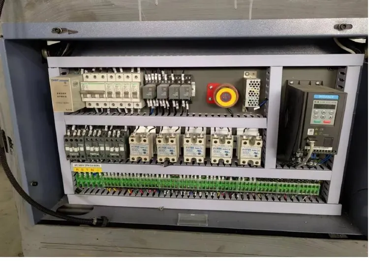
Under approved isolation, compare cable routing with the delivered cabinet and installation drawings. Check whether sensor, encoder, communication and low-level signal cables remain separated from motor, heater and other power conductors as designed. Inspect connectors, glands, shield terminations, bend points and flexible cable areas for damage or unauthorized changes.
Do not assume that connecting every shield at both ends—or only one end—is universally correct. The correct termination depends on the signal, device instructions and system design. Restore only the documented arrangement or obtain supplier confirmation. Keep replacement cables equivalent in required conductor, shield, temperature, flex and connector characteristics.
Correlate faults with power and switching events
Use suitable recording equipment at safe approved points to compare the event with control-supply variation, drive operation or load switching. The power quality and voltage imbalance guide provides the wider supply investigation. A short hand-held reading may miss a transient event; trend data is more useful when the fault is intermittent.
If the HMI loses communication, use the HMI and PLC communication guide to check device power, network state and configuration before changing grounding. If a drive trips, retain the exact drive code and investigate the delivered motor/drive system instead of treating every trip as noise.
Control modifications and replacement parts
Do not add capacitors, suppressors, ferrites, isolation devices or new earth conductors without engineering review. A part that reduces one symptom may create leakage current, overheating, communication problems or a new safety issue. Record the component specification, location, approval and rollback method for any authorized modification.
After a sensor, drive, power supply or cable is replaced, confirm model, pinout, parameter set, shield arrangement and routing against the controlled reference. Use the production change control guide so future technicians can distinguish the designed machine from an undocumented field modification.
Validate the complete operating state
Restore covers and guards before energizing. Test the machine through the approved sequence and repeat the operating event that previously preceded the fault, without defeating safety functions. Record alarms, diagnostic states and supply evidence through multiple cycles and the relevant warm-up or speed stages.
Electrical recovery is complete only when the machine sequence remains stable and finished cups pass the accepted checks. A disappeared alarm with a new intermittent feed or sealing defect is not a clean result. Retain the before/after evidence and electrical approver.
Frequently asked questions
Does a random sensor alarm prove electromagnetic interference?
No. A failing sensor, loose connector, unstable supply, damaged cable, contamination, sequence issue or mechanical target movement can produce the same alarm. Establish a repeatable correlation first.
Can the protective earth be disconnected briefly for testing?
No. Removing a protective safety path is not an acceptable interference test. Use qualified personnel, approved instruments and the applicable electrical procedure.
Should every cable shield be grounded at both ends?
There is no universal rule for every signal and machine. Follow the device manual and delivered system drawing, then confirm any change with the machine or control-system supplier.
What evidence is most useful for an intermittent interference claim?
Provide the first-event timeline, affected channel, exact alarms, machine state, load-switching correlation, power/control-supply trend, cable route photos, recent changes and qualified test results.
Send the machine model, electrical drawing revision, exact alarm timeline, affected devices, load correlation, cable photos and qualified measurements through our inquiry page. HANNAI can review the delivered control scope and help define the next safe diagnostic step.