Paper cup machine HMI and PLC communication troubleshooting should begin by separating a display problem from a controller, network, power or machine-sequence problem. A blank screen, frozen value, communication alarm and non-responsive command may look similar to an operator, but they do not prove the same failure. The safest and fastest diagnosis preserves the first evidence, identifies the delivered control architecture and tests one boundary at a time.
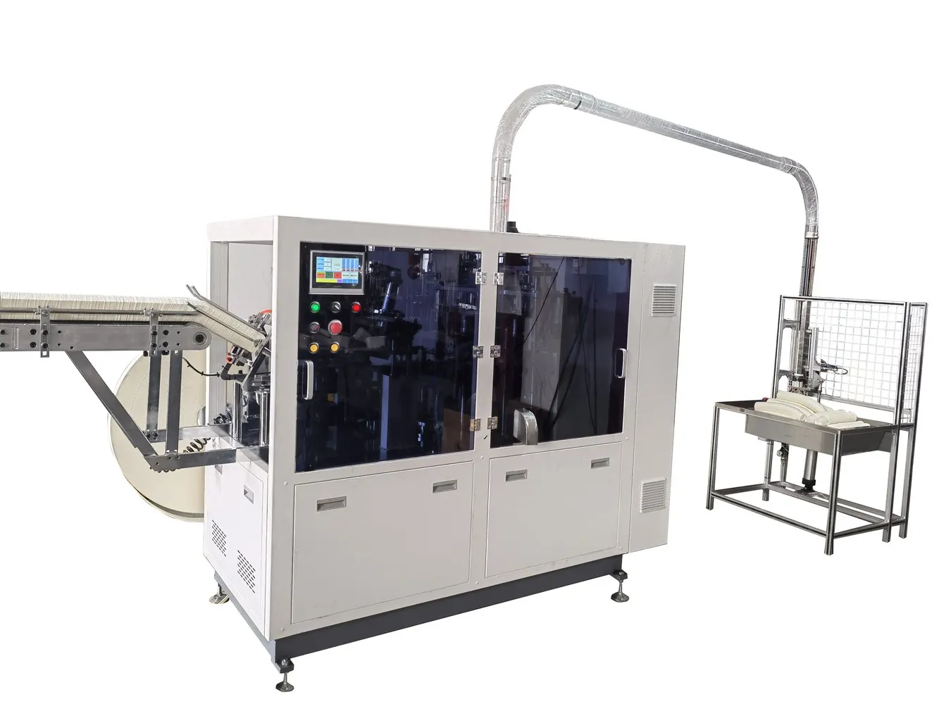
Define the symptom before changing anything
Record whether the HMI is dark, powered but stuck during startup, showing live values but rejecting commands, displaying question marks or stale data, or reporting a named controller or network fault. Note the machine mode, last completed station event, time of occurrence and whether the fault followed a power interruption, maintenance action, software change or component replacement.
A controller may continue its program while the operator panel has lost communication. Conversely, an HMI can remain visible while the PLC is stopped, faulted or waiting for a valid safety condition. Confirm what still works instead of treating the panel as proof of the entire control state.
Build a communication fault evidence table
| Observation point | Evidence to capture | What it helps distinguish |
|---|---|---|
| HMI state | Screen photo, displayed time, alarm text and responsive pages | Power, application startup or data-communication problem |
| PLC state | Controller indicators and approved diagnostic status | Running controller, stopped controller or controller fault |
| Network path | Device labels, switch indicators, connector condition and topology | Single cable, network segment or device-level issue |
| Power supply | Approved measurement at the correct terminals and time of fault | Stable supply versus interruption or voltage drop |
| Machine sequence | Interlock states, last motion and first alarm order | Communication failure versus valid process inhibit |
| Configuration | Program revision, address list, replacement history and backup | Hardware fault versus configuration mismatch |
| Recovery proof | Repeated cycles, alarm history and accepted cups | Temporary reset versus verified correction |
Map the delivered control architecture
Use the electrical drawings and equipment records to identify the HMI, PLC, remote input/output modules, drives, temperature controllers, safety controller where fitted, network switches and communication converters. Record the cable route and interface used by each device. Do not assume every paper cup machine uses the same protocol, address range or topology.
The technical documentation checklist explains which drawings, backups and device lists should remain under revision control. A simple architecture sketch often shows whether several missing devices share one power supply, one switch or one cable path.
Preserve the first alarm and event order
Do not repeatedly cycle power before recording the original condition. Capture the exact message, affected device name, panel page, controller status and indicator pattern. If several alarms appear, record their order; downstream stations frequently report secondary faults after the first communication path is lost.
Where the approved system provides alarm history or diagnostic logs, export or photograph them before clearing. Pair this evidence with the sensor and interlock troubleshooting guide so a legitimate missing permissive is not mistaken for a failed network.
Separate power, physical link and configuration
First confirm whether the affected devices have their intended power and normal status indication. Next inspect accessible network cables, locking tabs, strain relief, visible damage and switch-port indicators. Only then review addresses, device names, protocol settings and the relationship between the HMI project and PLC program.
Inspection or measurement inside an energized cabinet is restricted to qualified electrical personnel following the site’s risk assessment. Isolate and verify the safe state before reseating internal connectors. The electrical control cabinet inspection guide provides the companion boundary for heat, contamination, terminals and power-supply checks.
Use the fault pattern to narrow the boundary
If every screen value is stale but the controller remains in run, examine the HMI-to-PLC path. If one remote group disappears, identify the shared module, cable segment or supply. If communication fails only during a specific motion, look for cable movement, vibration, electromagnetic disturbance or supply sag associated with that event. If the fault began immediately after replacement, verify compatibility, configuration and address assignment against the controlled backup.
A fault that clears after a restart is not automatically repaired. Intermittent connector contact, heat, unstable power and duplicate addressing can return after production resumes. Record the environmental and operating conditions around each occurrence.
Control software, addresses and replacements
Before an authorized upload, download or parameter change, preserve dated copies of the HMI application, PLC program and relevant device settings. Confirm which direction transfers the approved project; an incorrect transfer can overwrite the only working configuration. Never use an online project from another machine merely because its hardware appears similar.
Replacement panels or controllers may require the correct model, firmware compatibility, application file, communication parameters and license or memory arrangements. These tasks belong to qualified automation personnel. Every change should be logged through a controlled approval and rollback process.
Check machine safety independently of the display
A normal-looking HMI does not prove that guards, emergency stops or safety circuits are healthy. Never bypass a safety input, force a PLC value or bridge a contact to make the machine run. Verify safety functions using the supplied procedure and personnel authorized for the delivered system.
Likewise, do not reach into the forming path to observe whether a command arrived. Use guarded observation, approved diagnostics and safe manual modes. Unexpected restart remains possible when communication is restored.
Prove recovery at the process level
After correcting the verified cause, restore guards and cabinet covers, confirm the approved software revision and clear tools from the machine. Test power-up, operator login where applicable, manual commands, alarm acknowledgement, recipe selection and each relevant station indication in the authorized order.
Then run staged cycles and confirm that live values update, commands act on the intended device, interlocks stop unsafe motion and accepted cups are produced repeatedly. For a configured machine such as the HN-SF160, the actual control architecture and acceptance test must follow the delivered documentation rather than a generic online procedure.
Frequently asked questions
Does a responsive HMI prove that the PLC is communicating correctly?
No. Local HMI pages may remain responsive while controller data is stale or one connected device is offline. Compare live timestamps, controller state and known changing values.
Should operators restart the machine whenever a communication alarm appears?
Only according to the approved operating procedure and after preserving evidence. Repeated restarts can erase the original alarm order and hide an intermittent power, cable or configuration fault.
Can a new HMI be installed with the old project’s settings automatically?
Not safely by assumption. Hardware revision, firmware, application, addresses and communication settings must be confirmed by qualified personnel against the controlled machine backup.
When should the machine supplier or automation specialist be involved?
Escalate before protected software changes, controller or panel replacement, address changes, forced values or safety-system work, and whenever the available drawings cannot establish a safe diagnostic boundary.
Send the machine model, controller and panel labels, exact alarm sequence, photos of status indicators, recent changes, electrical drawing reference and a guarded event video through our inquiry page. HANNAI can review the evidence and discuss the next controlled diagnostic step.