Paper cup machine hot-air nozzle and airflow maintenance applies only to configurations that use heated air for a forming or sealing step. Uneven heating, contamination, air leakage or a shifted nozzle can produce weak bonding, surface damage or speed-sensitive defects, but the same product symptom can also come from paper, coating, presentation or pressure. Diagnosis should prove heat delivery before anyone changes temperature or nozzle position.
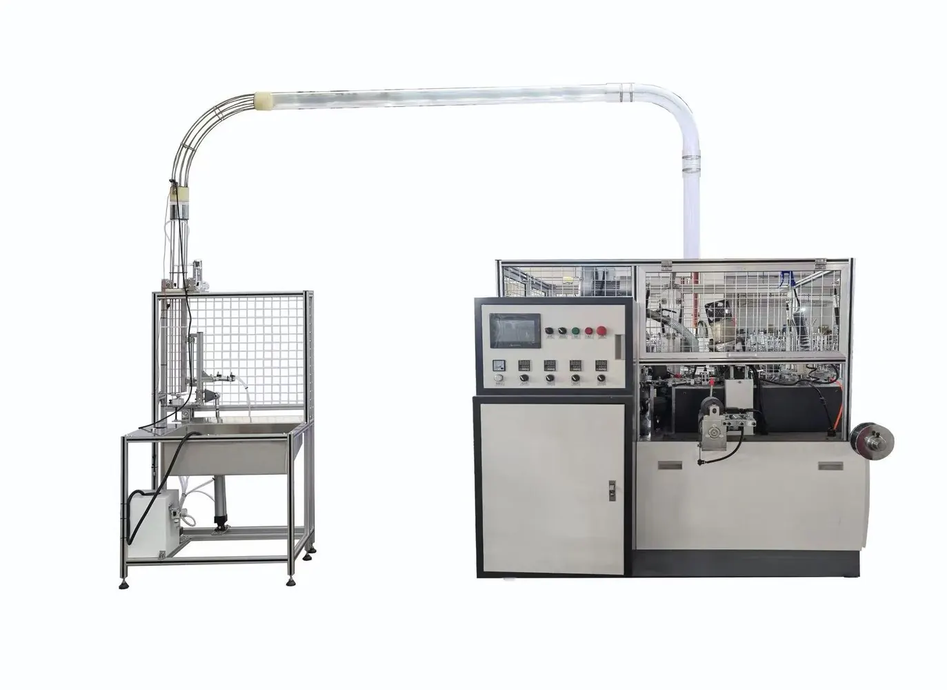
Confirm that the machine uses hot air at the affected step
Review the delivered process diagram, heater list, electrical drawings and pneumatic arrangement. Identify the heater, blower or air source, hose, manifold, nozzle and the exact product area being treated. Some paper cup machines use ultrasonic energy for a seam or a different heat method for another step, so do not apply a hot-air checklist to the wrong process.
The ultrasonic versus hot-air sealing guide explains the buyer-level distinction. At maintenance level, all setpoints, component limits and nozzle references must come from the delivered machine and material trial record.
Classify the product and machine evidence
Mark defects by product location and cycle order. Separate weak or open bonding, scorched or discolored material, coating disturbance, distortion, odor, intermittent sealing and a defect that appears only after acceleration. Retain good and bad samples with paper lot, coating side, cup format, time and machine state.
Record actual controller readings, heater-ready state, alarm history, air-source condition and warm-up sequence without changing them. A displayed temperature does not prove that air reaches the correct surface with the required distribution.
Use an airflow evidence table
| Observed pattern | Evidence to inspect | Diagnostic direction |
|---|---|---|
| Weak bond at one position | Defect map, nozzle outlet, cup presentation and local contamination | Check local airflow, alignment and product geometry |
| Defect begins after warm-up | Actual readings, controller trend, airflow and component expansion | Review temperature control and heat-related position change |
| Good at low speed, weak at normal speed | Cycle timing, treatment window, air delivery and motion completion | Separate insufficient process margin from mis-timing |
| Material scorches or deforms | Paper identity, coating, distance, exposure and controller evidence | Stop uncontrolled temperature increases and confirm the approved recipe |
| Heating varies across several stations | Shared air source, manifold, filter, leaks and supply condition | Trace the common utility before adjusting individual nozzles |
Inspect only after heat and stored energy are isolated
Follow the machine lockout and cool-down procedure. Heated surfaces, trapped pressure and nearby mechanisms can remain hazardous after the stop command. Verify that the nozzle and hose are safe to approach before removing guards or touching components.
Inspect the nozzle outlet for paper dust, coating residue, deformation, damage or an unauthorized modification. Check hose condition, clamps, seals, supports and evidence of rubbing or leakage. Preserve nozzle identity, installed orientation and reference marks before removal.
Clean and restore the delivered geometry
Use only the approved cleaning tool and method. Do not drill, scrape, grind or enlarge an outlet because that can permanently change airflow distribution. Replace a damaged nozzle with the confirmed part. Check that the support is secure and that the nozzle returns to its documented distance and orientation relative to the presented product.
Inspect the cup or blank presentation at the same time. A tilted body, variable height, unstable carrier or shifted guide changes heat exposure even when the nozzle is correct. Link this check with the heating and temperature control guide rather than changing mechanical and temperature variables together.
Trace shared airflow and control conditions
Check filters, regulators, blower inlets, manifolds and visible hoses included in the configuration. Record supply condition under the permitted operating state. A pressure reading at rest may not represent flow during the machine cycle, and one restricted branch can behave differently from a common supply fault.
Qualified electrical personnel should review heater current, sensor integrity, controller output and alarms where needed. Never bypass temperature protection or raise the setpoint beyond the approved recipe to compensate for a leak, restriction or bad product presentation.
Prove the correction with material evidence
Restore guards, clear tools and use the approved restart and warm-up sequence. Run identified samples at controlled stages. Record actual readings, machine condition and consecutive product results. Change only one authorized variable at a time so the effect can be understood.
Verify bonding or forming quality with the product test specified for the application, not appearance alone. Retain samples and confirm that the correction remains stable after the machine reaches normal operating condition.
Frequently asked questions
Should temperature be increased when a hot-air seal is weak?
Not before checking material, airflow, nozzle condition, presentation and cycle timing. A higher setpoint may damage coating or hide a restriction without restoring a controlled process.
Can a clogged nozzle be opened with a drill bit?
No unless an approved supplier repair procedure explicitly requires it. Enlarging or scratching an outlet changes airflow and can make heating less uniform.
Why is the product good at low speed but weak after acceleration?
The treatment window, cup stability, airflow under demand or motion completion may have insufficient margin. Record cycle evidence and verify the delivered recipe instead of guessing one parameter.
What should be sent to the machine supplier?
Send the machine model, cup format, paper and coating identity, defect map, heater and air-source readings, alarm history, safe nozzle photographs, cycle video and recent maintenance changes.
Send the machine model, cup drawing, material and coating, affected station, recipe evidence, defect samples and a safe cycle video through our inquiry page. HANNAI can review the evidence against the delivered heating configuration.