Paper cup machine heating and temperature control affect sealing stability, startup preparation, energy use and repeatability. A professional control plan links the heat source, sensor, controller, airflow, machine speed, material and observed cup result instead of relying on one displayed number.
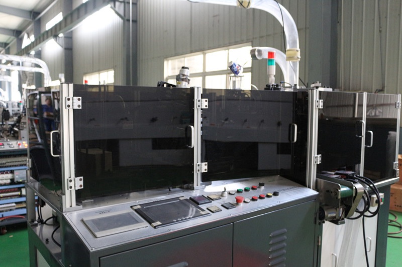
Define the complete heating loop
Identify the heat source, power switching component, temperature sensor, controller, air path or contact point, mechanical position and cooled or guarded areas. Hot-air systems, resistance heaters and other supplied arrangements do not share one universal setting or inspection method.
The finished seal is produced by the combined process. Temperature alone cannot compensate for incorrect material, poor alignment, insufficient contact, unstable airflow or an unsuitable speed.
Build a heating control evidence table
| Control point | Evidence to define | Decision question |
|---|---|---|
| Configuration | Machine, cup format, material, coating and sealing method | Is the approved recipe being used? |
| Heat source | Zone identity, heater condition and power command | Is the intended zone delivering heat? |
| Measurement | Sensor type, location, reading and verification status | Does the reading represent the process point? |
| Air or contact | Flow path, nozzle/contact position and obstruction | Is heat reaching the correct area consistently? |
| Production state | Warm-up time, speed, stops, restarts and ambient condition | Is the comparison made under the same state? |
| Quality result | Seal appearance, leakage evidence and affected station | Does the cup meet the approved acceptance plan? |
Start from the approved material and cup format
Record paper grade, coating structure, blank dimensions, bottom material, cup size and the supplied machine configuration. A setting used for one structure should not be copied automatically to another. Material and geometry changes can alter heat transfer and the available sealing window.
Use the pre-production sample approval checklist to keep the recipe connected to an accepted cup rather than an operator’s memory.
Verify the displayed value before adjusting it
Confirm the correct zone is selected and allow the system to reach its defined ready condition. Compare controller status, sensor response, alarm state and, where the factory procedure requires it, an authorized independent measurement.
A stable display does not prove correct heat delivery. A displaced sensor, loose connection, worn heater, switching problem, restricted air path or wrong zone assignment can create a misleading value. Electrical checks must be performed by qualified personnel under safe isolation procedures.
Inspect airflow, nozzles and contact position
Where hot air is used, review blower condition, hose integrity, filters, nozzles, leakage and position. Paper dust or a shifted component may change distribution even when controller temperature is unchanged. Where contact heating is used, inspect the approved contact surface, pressure and alignment.
Do not move a nozzle or heating component without recording its original reference. Heat directed at the wrong location can damage material, nearby components or guarding while leaving the intended seal unstable.
Control warm-up, stops and restarts
Define when heat is enabled, what “ready” means, how long material may remain exposed during a stop, and how the machine returns after an interruption. First cups after startup or a long stop may require a controlled inspection window.
The planned shutdown and restart guide helps coordinate heat, drives, air, material and quality release rather than treating temperature as an isolated control.
Adjust one controlled variable at a time
When a seal result changes, preserve the current settings and sample first. Check material identity, machine speed, position, pressure, airflow and mechanism condition. If a temperature change is authorized, make a defined step and record the resulting cups.
Avoid repeated unrecorded increases. Excess heat can deform or discolor paper, contaminate components, shorten component life or narrow the process window without correcting the true cause.
Connect temperature data to cup-quality evidence
Record actual displayed values, zone, time, speed, sample identity and inspection result. Keep failed and accepted samples where required. The paper cup leakage and quality checklist supports a broader evaluation of seam and bottom performance.
For a machine such as the HN-S120, final heating arrangements and values remain configuration-dependent. The supplied manual and project-specific commissioning record are the controlling references.
Frequently asked questions
Is the highest stable temperature the best production setting?
No. The approved setting must produce acceptable cups without unnecessary thermal load. Material, speed, airflow, contact and mechanism position all affect the usable process window.
Why can seal quality change when the display remains stable?
The display represents a sensor location, not every part of the heat path. Heater output, switching, airflow, nozzle position, contamination, speed, pressure or material may have changed.
Can an infrared thermometer replace the installed sensor?
Not automatically. Surface emissivity, viewing position and response differ. Any independent tool must be suitable for the defined measurement and used under the approved safety and verification procedure.
When should a heating setting be reapproved?
Review changes to material, cup geometry, heater, sensor, controller, air path, sealing mechanism, speed or approved maintenance work and document the release decision.
Send your cup drawing, paper and coating, machine model, sealing method, current settings, alarm evidence and sample photos through our inquiry page. HANNAI can discuss configuration-dependent checks and sample preparation.