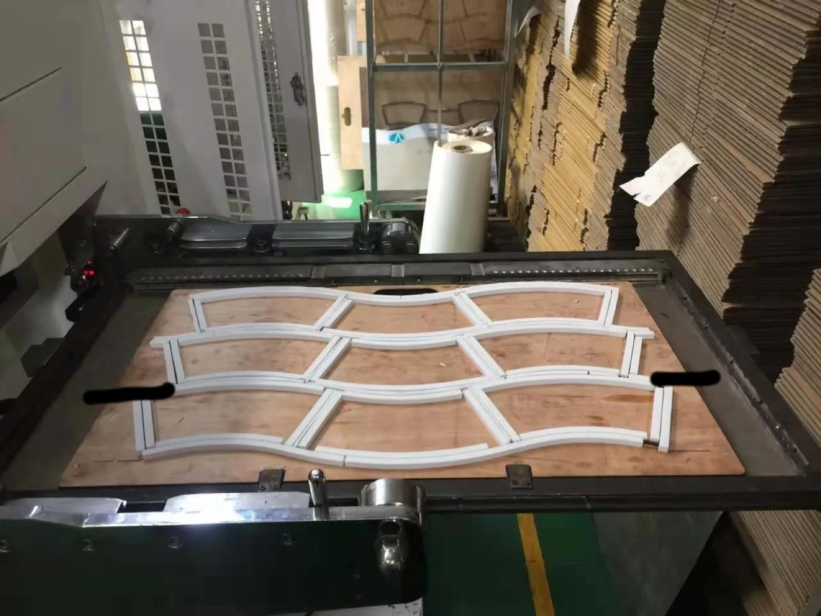
Roll-fed describes how paper enters a die-cutting machine. It does not specify whether cutting is flatbed or rotary. This distinction matters before inspecting a tool edge or choosing mounting instructions. A flat cutting die and a rotary die cylinder have different supporting surfaces, retention methods and setup references.
Establish the actual cutting construction
The KN-950 reference specification identifies the illustrated machine as a roll-fed flatbed die cutter. A reel feeding the machine is therefore not evidence that its cutting tool is a rotating cylinder. Its listed maximum cutting size is an area; its cycle rating must not be confused with the number of individual blanks delivered.
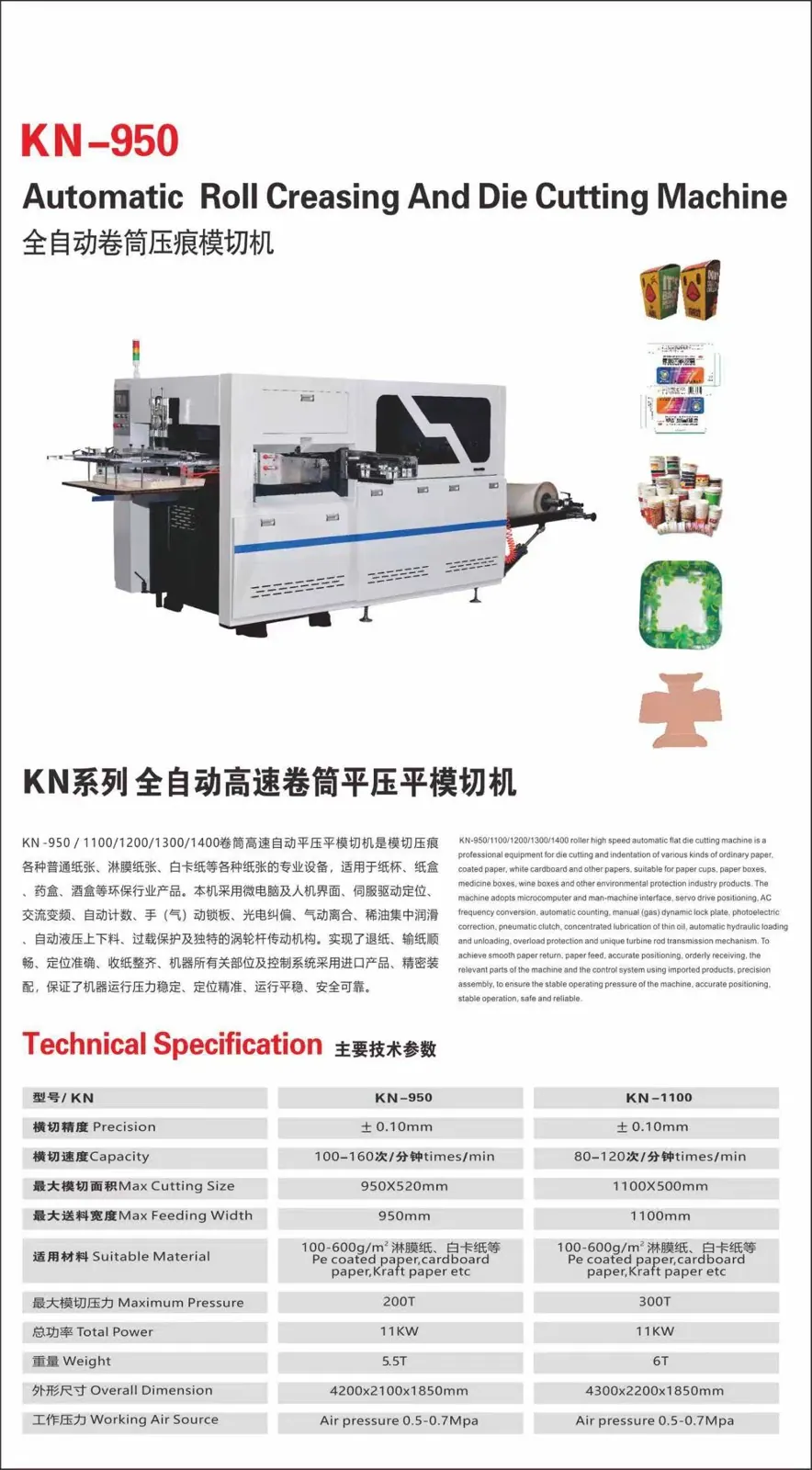
For another model, obtain the machine and tooling drawings before assigning a construction. Do not use magnetic-cylinder or rotary-anvil instructions merely because the equipment is called a roll die cutter. The 950 product page provides the corresponding reference sheet; final tooling and material suitability still require the supplied configuration.
| Construction | Identify before inspection | Do not assume |
|---|---|---|
| Roll-fed flatbed | Die board or supplied flat tool, mounting frame and opposing cutting surface | A magnetic cylinder or rotary die is fitted |
| Rotary cutting system | Actual cutting cylinder, tool type and mating support | Flatbed mounting methods apply |
| Flexible die system | Confirmed flexible plate and compatible magnetic cylinder | Every rotary cutter uses flexible dies |
Map the defect to the tool and material
Keep identified acceptable and defective blanks from the same roll. Mark feed direction, cross-web position and the feature affected. Distinguish incomplete cutting, crushed edges, nicks and print-to-cut displacement. A repeated defect at one feature gives a useful location to inspect; it does not prove the cutting edge is the only cause.
Compare the supplied die layout, material specification and cutting-pressure/alignment record. Increased machine force is not a substitute for checking incorrect tooling, contamination or a damaged supporting surface.
Inspect only through the appropriate tooling procedure
Qualified personnel must establish the safe isolated condition before guarded access, tool removal or contact with cutting edges. Use the lifting, mounting and inspection method for the actual tool. Do not grind, file, shim or retension a tool from a generic article.
For a flatbed, record the die identity, mounting and opposing-surface findings required by its documentation. For a confirmed rotary system, record the relevant cylinder and tool references. Keep construction-specific findings separate rather than using one checklist as proof for both systems.
Validate the cut and downstream blank
After authorized work and restoration of guards, compare trial blanks with the approved drawing. Check cut completeness, geometry, artwork position and delivery condition under the agreed method. Good print register does not prove an acceptable edge, and one good blank does not characterize an entire lot.
Send HANNAI the machine nameplate, tooling photograph and marked samples. Those references allow a configuration discussion without assuming that an unseen machine contains a particular tool system.
Frequently asked questions
Does roll-fed mean rotary?
No. Roll-fed identifies material supply. Cutting construction must be identified separately.
Does the KN-950 sheet establish a magnetic-cylinder system?
No. The available reference identifies flatbed cutting and does not establish a flexible-die or magnetic-cylinder option.
Should more cutting force be the first response to a local defect?
No. Retain samples and inspect the correct tool and support references before an authorized adjustment.
What should accompany a tool problem report?
Machine and tool identity, material lot, mapped blanks, the first observed defect and the actual setup and inspection records.