A paper cup packing machine pusher must transfer a counted cup stack into the prepared film or bag at the correct point in the sequence. A slow cylinder, miscentered stack, early film movement or missing completion signal can cause crushed rims, partial insertion, double cycles or a machine stop. Troubleshooting should follow the handshake from stack ready through pusher return instead of increasing air pressure or sensor delay without evidence.
Write the expected sequence in signal order
Use the machine sequence description and I/O list to identify stack-ready, bag-ready or film-position, pusher-home, pusher-forward, seal-area-clear and fault-reset signals. Record the valve, cylinder, guides and mechanical stops involved in each step.
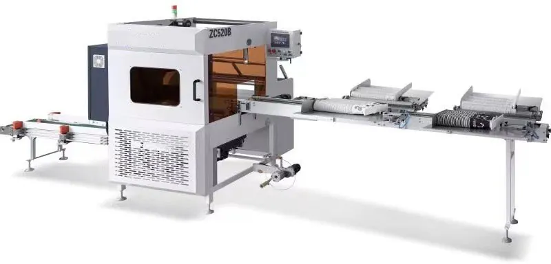
The paper cup packing machine page provides the equipment context. Actual stack length, bag format, cylinder speed and sensor positions remain project-specific.
Preserve the failed pack and event order
Label the affected cup stack, film or bag and time of failure. Record whether rims collapsed, the stack tilted, the pusher stopped short, film moved early or the return signal did not arrive. Safe slow-motion video from outside guards can reveal which event changed first.
Note cup size, stack count, cup nesting behavior, film lot, air indication, machine speed and recent changeover. Do not clear all evidence before photographing stack and pusher positions.
Use a pusher-sequence evidence table
| Observed condition | Evidence to inspect | Diagnostic direction |
|---|---|---|
| Pusher starts before stack is centered | Stack-ready sensor, guides, count completion and sequence logic | Verify the preparation handshake |
| Pusher stops before full insertion | Loaded pressure, cylinder travel, obstruction, flow and forward signal | Separate force, restriction and position causes |
| Cup rims crush during entry | Pusher face, stack alignment, bag opening and insertion path | Inspect geometry before changing speed |
| Machine waits after successful push | Forward or return sensor, valve state and PLC input | Trace completion feedback |
| Fault appears only with one cup size | Change parts, guide setting, stack length and nesting | Review product-specific setup |
Control stored pneumatic and mechanical energy
Apply lockout, vent the relevant air circuit and verify the pusher cannot move from trapped pressure, gravity or springs. Secure film and cup stacks where they can fall or release. Use the approved blocking method before entering the pusher path.
Photograph sensor brackets, cylinder position, flow controls, guide settings, stops and pusher-face orientation before adjustment. Never use a manual valve override while a person is inside the guarded zone.
Inspect cup-stack preparation and alignment
Check that the count is complete, cups are fully nested, rims are not already damaged and the stack sits against the intended side and height references. Inspect guides, rails, stops and the transfer surface for buildup, looseness or wear. Compare different cup sizes only after installing the approved change parts.
A wandering or springy stack can load the pusher unevenly. Confirm upstream counting and collection release before treating the cylinder as the primary fault.
Inspect pusher mechanics and cylinder travel
With energy controlled, inspect the pusher face, rod, coupling, guides, bearings and stops for looseness, bending, scoring, play or collision marks. Verify unloaded travel through the documented service method and check that the pusher remains centered through its stroke.
Inspect cylinder mounting and rod side load. A cylinder may extend freely when disconnected from the mechanism but slow under misalignment or cup-stack load.
Check valve, airflow and flow controls
Record pressure behavior while the pusher moves under a representative controlled load. Inspect valve response, tubing, fittings, silencers and flow-control orientation. A static regulator indication does not prove adequate flow during acceleration.
Do not increase pressure beyond the delivered range or fully open flow controls to force the sequence. Higher impact can damage cups, guides and cylinder stops while hiding a restriction.
Verify sensors and PLC handshakes
Confirm home and forward targets pass through the intended sensing zone and that sensor indicators match the PLC inputs. Inspect brackets, cables and target looseness. Record input order for a good and failed cycle using the approved diagnostic view.
Use the film feeding, tracking and cutting guide if the bag or film is not ready when the pusher receives permission. The pusher cannot correct an incomplete film-preparation sequence.
Prove one complete cycle at a time
After approved correction, restore all guards and run the manual or slow-cycle process with an empty path first if permitted, then with labeled cup stacks. Confirm stack ready, film ready, pusher forward, completion, return and release occur once in the intended order.
Increase count, cup size range and operating speed in stages. Inspect cup rims, bag entry, pusher-face contact and sensor repeatability. Record settings, sample packs and the final accepted sequence.
Frequently asked questions
Should air pressure be increased when the pusher stops short?
No. First check obstruction, alignment, cylinder condition, flow restriction, stack load and the approved pressure range.
Can sensor delay solve repeated bagging faults?
Only after the real event order is understood. Added delay can hide slow mechanics or create another collision.
Why does the problem appear only with taller stacks?
Stack stability, nesting, guide support, insertion friction and delivered format settings may change with stack length.
What evidence helps supplier diagnosis?
Provide cup and stack details, failed packs, sequence input video, cylinder and guide photos, loaded air behavior and current changeover settings.
Send the machine and pack format, cup-stack details, failed-pack photos, sequence evidence, cylinder observations and air behavior through our inquiry page. HANNAI can review the handshake for the supplied packing setup.