A replacement motor must fit the electrical supply, drive, mounting and mechanical load as one system. Matching only power on the nameplate can leave the wrong speed, current, frame, shaft, brake, enclosure or feedback interface.
This checklist is intended for procurement and commissioning control. It does not authorize changes to motor sizing, guarding or control design. Lock out hazardous energy, support connected loads and use qualified electrical and mechanical technicians.
Decision matrix
| Compatibility group | Evidence | Decision |
|---|---|---|
| Electrical | Voltage, phase, frequency, current, connection and insulation | Match supply or drive application |
| Performance | Rated power, speed, torque/duty and service conditions | Confirm load and cycle suitability |
| Mechanical | Frame, mounting, shaft, key, flange and mass | Fit without improvised machining |
| Integrated devices | Brake, encoder, fan, thermostat and connector | Match control and feedback interfaces |
| Commissioning | Drive data, rotation, alignment, current and temperature | Prove stable operation under controlled load |
Capture the complete installed assembly
Photograph the whole nameplate, mounting, terminal box, shaft connection and auxiliary devices. Record motor manufacturer, model, serial, rated data, frame and mounting arrangement. Inspect whether a gearbox, brake, encoder or separate cooling fan is part of the assembly.
ABB nameplate guidance shows why voltage, frequency, current, speed, frame and enclosure information all matter. For a variable-frequency drive application, also obtain the motor and drive manuals and the current parameter set. Do not infer suitability from power and exterior size alone.
Match mechanical interfaces and load
Measure and confirm shaft diameter and length, key, flange pilot, bolt pattern, mounting feet, center height and available envelope from controlled drawings. Check coupling, pulley or gearbox input limits and how the driven load is supported during removal.
A makeshift adapter can change alignment, overhung load, cooling clearance or guard fit. Review rated speed and the actual machine transmission together. If replacement changes inertia, torque curve or base speed, machine timing and stopping behavior may also require formal engineering validation.
Match electrical and control functions
Confirm supply or inverter output voltage, phase, frequency range, connection diagram, rated current and motor insulation suitability for the drive application. Record thermistor, thermostat, brake coil, encoder and fan requirements with their pinouts and supply ratings.
Enter motor data in the drive only according to the approved commissioning procedure. Preserve the original drive backup before changes. Automatic identification or tuning routines may move the shaft or require it to be uncoupled; follow the drive manual and machine risk controls.
Install, align and test direction safely
Inspect base flatness, fasteners, coupling condition and driven-shaft freedom. Align using the approved tolerance and method, then restore guards. Verify protective earth and terminal tightness with the specified hardware and torque process.
Use a controlled bump or setup test to confirm rotation only when the machine procedure permits it. A reversed motor can damage timing-sensitive mechanisms. Observe current balance, noise, vibration, cooling airflow and bearing temperature during staged operation without assigning generic limits to an unknown motor.
Close the change with traceability
Record old and new motor data, compatibility review, drive parameter comparison, alignment readings and test results. Update the spare-parts list and electrical drawing if an approved design change was made.
When requesting HANNAI review, send the machine and project reference, full nameplates, motor and drive photos, mounting drawing, shaft interface and reason for replacement. Use the linked alignment guide before blaming a new motor for coupling vibration.
Technical references
- ABB guide to motor nameplate data — general component guidance; the installed machine documentation remains controlling.
Related machine and guide
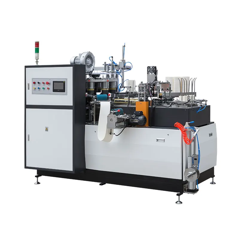
Review the HN-M100 automatic paper cup machine for machine context, then use the coupling and shaft alignment guide for the adjacent check. Browse all Buyer Guides when building a wider project checklist.
Frequently asked questions
Is equal kilowatt rating enough for replacement?
No. Electrical, speed, duty, frame, shaft, auxiliaries, drive and load compatibility must also be confirmed.
Can old drive parameters be kept automatically?
Only if the approved review confirms the replacement motor data and control method match; preserve a backup first.
Why test rotation before full production?
Wrong phase sequence or command logic can reverse motion and damage timing-dependent mechanisms.
What evidence should accompany a motor inquiry?
Send complete nameplates, mounting and shaft drawings, drive model, auxiliary devices, photos and operating symptoms.
Review your machine configuration with HANNAI
Send the machine model, project reference, component labels, drawings, photos and a description of the required result. We will clarify which details must be confirmed before a quotation or technical recommendation.