Roll die cutter dancer calibration establishes how the controller interprets the position of a moving web-handling arm. If the sensor direction or travel scaling is wrong, adjusting tension-control gain can hide the error briefly while leaving unstable behavior at startup or near a travel limit.
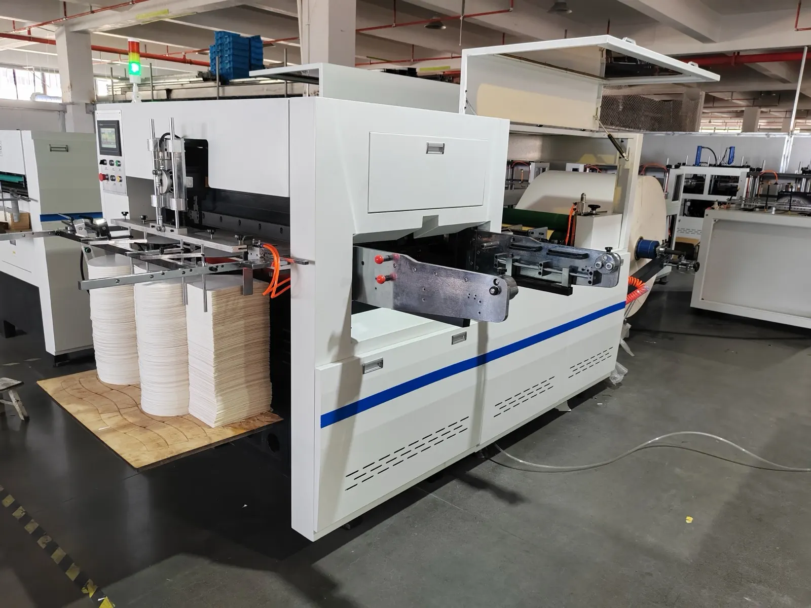
Use this guide only when the delivered line has a dancer and position feedback. A load-cell-only tension system requires a different calibration. The reference photograph shows a roll-fed die cutter, not confirmation of a dancer on every machine configuration.
Diagnostic decision table
| Observation | Check before tuning | Record |
|---|---|---|
| Displayed direction opposes arm motion | Sensor direction and control definition | Position versus input indication |
| Display reaches its limit too early | Sensor travel and scaling | Approved endpoints and readings |
| Arm jumps despite smooth mechanics | Signal continuity or input fault | Repeatability through travel |
| Position looks stable but tension is wrong | Dancer loading and web geometry | Actual loading and web path |
Separate position measurement from web tension
Draw the web path and identify the dancer arm, loading mechanism, sensor and controlled brake or drive. Record whether the controller regulates arm position through a torque or speed output. Do not treat a position percentage as a direct tension measurement.
The dancer loading and web geometry influence tension, while the feedback loop attempts to maintain the selected position. Maxcess documentation distinguishes dancer input calibration from tuning and other configuration steps. That distinction is important after a sensor replacement: first establish a trustworthy position signal, then evaluate control response.
Back up the controller and inspect the mechanism
Save the current controller configuration, sensor identity and approved setpoint before changes. Record software version and any recent work on the arm linkage. Protect rolls and release stored web or pneumatic energy according to the machine procedure before physical inspection.
Check bearings, linkage, stops and sensor coupling for free movement and secure attachment. A bent bracket or slipping coupling cannot be corrected by changing endpoint numbers. Do not use the sensor body as a mechanical stop. If travel is restricted, resolve that condition before attempting an electrical calibration.
Use the approved travel and signal definitions
Qualified personnel should follow the installed controller procedure for its input type and safe calibration state. Identify which physical positions correspond to the documented low and high signals. Preserve the sensor operating range; do not force the arm beyond its intended stops to obtain an attractive display value.
Record readings at the specified points and compare repeat passes through travel. A signal that jumps or fails to return consistently needs investigation before scaling. Verify wiring and supply through the correct electrical procedure, keeping all control and safety functions intact. Do not copy voltage values from another controller model.
Check setpoint and correction direction separately
Determine whether the operating position setpoint comes from a local setting, an analog input or a network command. Some systems require the external setpoint path to be calibrated independently. A correct sensor input can coexist with an incorrectly scaled requested position.
Before allowing production, have the commissioning procedure verify the intended corrective direction and output limits. A control action that drives the arm farther toward its limit requires an immediate controlled stop and review. Do not bypass limit protection or increase tuning gain in an attempt to overcome a sign or mapping error.
Validate across a representative roll condition
Restore guards and run the approved startup sequence with suitable material. Compare arm position, register quality and any independent tension indication during acceleration, steady running and stopping. Use representative reel conditions rather than judging the system from a brief unloaded demonstration.
If oscillation remains after calibration is verified, investigate loading, friction, drive response and tuning as separate factors. Keep old and new settings, endpoint evidence, reel identity and the observed response together. Send HANNAI the control architecture and before-and-after trend so calibration errors can be separated from mechanical or loop-response problems.
Related equipment and next checks
Review the roll die cutting equipment and the related guide to web tension and register control. The Engineering Notes archive connects these checks with wider machine planning.
Technical reference
- Maxcess MAGPOWR dancer calibration and control documentation — general reference; confirm applicability to the installed equipment.
Frequently asked questions
Is dancer position the same as web tension?
No. Position feedback and dancer loading have different roles.
Should gain be adjusted before checking sensor scaling?
No. Establish correct and repeatable feedback first.
Does every roll die cutter have a dancer?
No. Confirm the actual control architecture.
Must a remote setpoint also be checked?
Yes, when that input is part of the installed control arrangement.
Review the evidence with HANNAI
Send your machine model, component identification and the observations described in this guide. Include the drawing or material reference and any before-and-after measurements so the required next check can be identified.