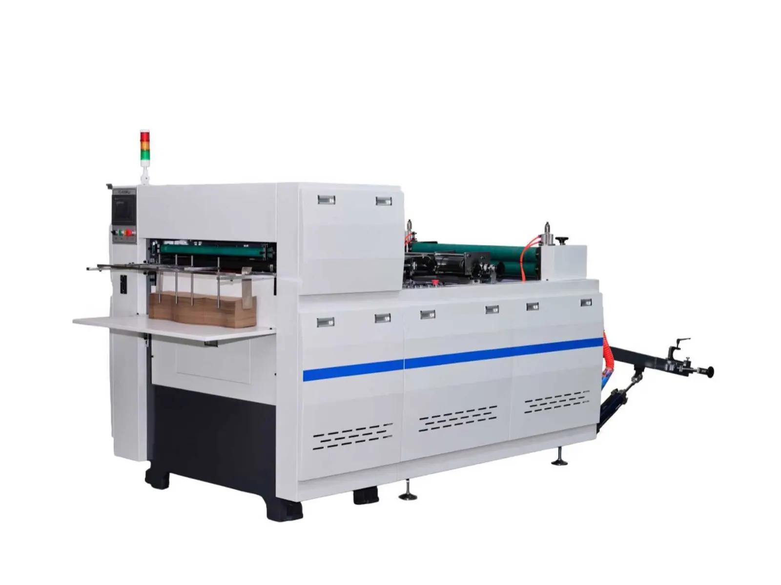
Roll die-cutting machine web tension and register control should be diagnosed as one connected material-handling process: the reel must unwind predictably, follow a stable web path, respond to guidance, present the printed repeat at the correct phase and enter the cutting station without slip or distortion. A paper cup fan blank that drifts, rotates or cuts off-register is therefore not automatically a tooling problem. The evidence must show where control was first lost.
Define the defect before adjusting the machine
Retain affected blanks in their production order and mark the machine direction, operator side, reel identity, time and operating state. Record whether the cut error moves gradually across the web, repeats at a regular interval, changes after acceleration, affects one lane or the full width, or begins near a reel splice. Also distinguish print-to-cut error from blank dimension, edge quality, crease position and sheet distortion.
Use the approved drawing or reference sample to identify the controlled feature. The paper cup blank die-cutting guide explains the downstream importance of fan geometry, while this guide concentrates on web transport and register evidence.
Map the actual web path and control zones
Trace the delivered line from the parent reel through unwind components, rollers, any dancer or tension-sensing device, edge or line guide, print-mark sensor, driven nip or feed section and die-cutting station. Label which elements are driven, which are passive and where the web can be influenced. Do not assume that another machine uses the same control architecture.
Preserve the approved threading diagram and photograph the correct route during a stable run. An omitted roller, incorrect wrap direction or web passing on the wrong side of a sensor can change traction and geometry even when the web still moves through the machine.
Build a register-loss evidence table
| Observation | Evidence to capture | Control question |
|---|---|---|
| Reel and splice | Material code, reel width, winding condition, splice position and orientation | Did the symptom begin with a specific reel condition or splice? |
| Web path | Threading photos, roller condition, wrap direction and contact marks | Is the web following the documented path without obstruction or slip? |
| Tension behavior | Approved display trend, dancer position or repeatable physical observations | Where does tension first become unstable? |
| Tracking | Edge position at defined checkpoints and guide response | Is lateral correction stable, saturated or reacting to a false reference? |
| Register detection | Printed mark quality, sensor view, input indication and detection consistency | Is each intended mark detected once and at a stable phase? |
| Cut result | Sequential blanks, print-to-cut offset, lane and machine-direction labels | Is the error gradual, cyclic, sudden or lane-specific? |
| Operating state | Start, acceleration, steady run, deceleration, restart and speed-change notes | Does the fault correlate with a transition rather than steady production? |
| Recovery proof | Controlled run record, retained samples and inspection approval | Was stable transport and acceptable blank quality demonstrated together? |
Inspect the reel and unwind condition first
An unevenly wound reel, damaged edge, telescoping, loose layers, incorrect mounting, poor core support or inconsistent splice can introduce disturbance before the register system has a chance to correct it. Under the machine’s approved stop and isolation procedure, inspect reel seating, unwind components, contact surfaces and evidence of rubbing. Confirm that the material identity matches the job record.
Do not compensate for a visibly unstable reel by increasing a generic tension value. The correct target and adjustment method depend on the material, web width, reel condition and delivered control system; they must come from the supplier documentation and verified process setup.
Separate tension instability from lateral tracking
Machine-direction tension and cross-machine tracking are related but different. Tension instability can stretch, relax or change the feed phase. Tracking error moves the web sideways and may change the cut relationship differently across the width. Mark fixed observation points along the safe, guarded path and determine where the deviation first appears.
If the guide is continually at its travel limit, first inspect web centering, sensor reference, actuator movement, roller alignment and upstream steering forces. Repeated manual correction can hide the origin and create oscillation. Adjustments near a moving web, nip or cutting system must follow the manufacturer’s safe procedure and be performed only by authorized personnel.
Verify print-mark detection before changing register
Check that the intended register mark has adequate contrast and a clear detection area for the fitted sensor. Observe the approved input indication across multiple repeats. Look for missing marks, extra graphic elements, contamination, wrinkles, reflective variation or a sensor position that allows the wrong feature to trigger.
The artwork itself should provide a controlled mark and repeat relationship. Use the paper cup printing artwork registration checklist to review mark placement, graphic clearance and print evidence before treating every detection problem as a machine fault.
Compare error patterns with the machine state
A gradual machine-direction drift can point toward accumulating phase error, changing tension or slip. A single sudden offset may align with a splice, restart, loss of detection or disturbance in the web path. A cyclic variation can correlate with a reel, roller or repeated print condition. Error that appears mainly during acceleration or deceleration deserves separate evidence from steady production.
Preserve chronological samples rather than selecting only the worst blank. The pattern across a sequence is often more diagnostic than one measurement. When comparing an 850 roll die-cutting machine with a 950 roll die-cutting machine, use each delivered machine’s control design and job range rather than transferring settings by nameplate category.
Check transport mechanics without masking the cause
Under approved lockout, inspect accessible rollers, bearings, driven nips, belts, couplings and contact surfaces for contamination, wear, looseness, abnormal marks or uneven pressure. A slipping transport component can produce an apparent register problem even when the sensor detects correctly. A mechanically tight component can disturb tension and load as speed changes.
Do not increase nip force, change drive parameters or move the cutting phase until evidence separates detection, transport and tooling. Record the original condition, authorize changes one at a time and retain a rollback reference. Guards, stored energy and sharp cutting components require qualified maintenance personnel.
Prove both register stability and blank quality
After correcting a verified cause, restore all guards and use the documented threading and startup sequence. Observe the approved low-risk stage, then collect consecutive samples during the authorized acceleration and stable run. Inspect print-to-cut relationship, blank profile, edges, crease features and any lane-to-lane difference against the approved sample or drawing.
Release should include the reel and job identity, corrective action, controlled setting record, sample sequence, inspection result and approver. A stable sensor display alone is not proof if the blanks remain distorted or the cut is unacceptable.
Frequently asked questions
Does an off-register blank mean the cutting die is installed incorrectly?
Not necessarily. Web tension, tracking, register-mark detection, transport slip, reel disturbance and the print repeat can all shift the print-to-cut relationship. Determine where the error begins before changing the tooling.
Can one tension setting be used for every paper reel?
No universal value should be assumed. Material construction, coating, width, reel build, print condition and the delivered tension-control arrangement can change the appropriate setup. Use the approved supplier and process references.
Why does registration become unstable mainly during acceleration?
Acceleration changes inertia, transport load and the response required from unwind, tension and register controls. Capture the approved control indications and sequential samples during the transition so the responsible zone can be identified.
When should HANNAI or a qualified service engineer review the fault?
Escalate when register detection is inconsistent, the web path cannot be stabilized, a drive or control change is proposed, the cutting area requires intervention, or the plant cannot establish a safe and documented cause from the delivered manuals.
Send the machine model, material and reel details, printed mark and artwork information, web-path photos, event video, sequential blank samples and recent change history through our inquiry page. HANNAI can review the available evidence and discuss a controlled next step.