A cabinet entry should seal and support the cable while preserving the intended shield and grounding design. An oversized gland, cut braid, sharp bend or long shield pigtail can admit dust, transfer pull to terminals or increase interference on encoder and sensor circuits.
Cable work must maintain enclosure protection, conductor insulation and separation between power and signals. Isolate energy and use the exact cable, gland and drive/sensor documentation. This guide does not impose one shield connection method on every circuit.
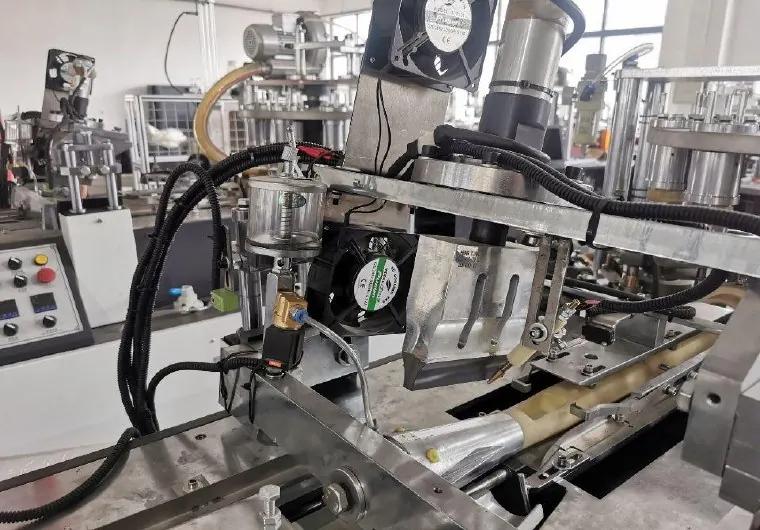
Decision matrix
| Entry factor | Evidence | Acceptance |
|---|---|---|
| Cable/gland fit | Cable diameter, gland range, thread and seal | Secure grip without insulation damage |
| Strain relief | Pull path, clamp and terminal loading | No movement reaches conductors |
| Shield | Braid condition, contact method and connection location | Matches the EMC design |
| Routing | Bend radius, heat/motion exposure and separation | Avoids damage and coupling |
| Enclosure | Blanking plugs, seals and entry plate condition | Maintains intended cabinet protection |
Map cable function before disassembly
Identify whether the cable carries mains, motor output, brake, encoder, analog signal, communication, sensor power or protective earth. Mark both ends and photograph shield and drain-wire treatment. The correct termination can differ by signal and drive manufacturer.
Trace the cable route and recent changes. A fault after machine relocation may come from stretched glands, swapped entries or shield bonds changed during reconnection. Do not remove several similar cables without a verified label map.
Match gland and cable construction
Confirm entry thread, cable outside diameter range, sealing insert, material, temperature and environmental requirement. Multi-cable entries and armored or shielded cables need their designed components. Do not wrap tape around a small cable to make it fit a larger gland.
Phoenix Contact EMC gland guidance uses controlled contact between braid and spring. Preserve adequate braid without loose strands touching conductors. Tightening torque and preparation length remain product-specific.
Restore strain relief and sealing
Inspect jacket for cuts, compression, oil or heat damage. The gland should grip the correct jacket area and prevent pull or twist from reaching terminals. Provide external clamps or flexible routing where the machine design requires them.
Check entry-plate holes, locknuts, O-rings and unused openings. Fit approved blanking plugs instead of improvised sealant. Avoid over-tightening that deforms cable insulation or damages the entry thread.
Preserve shield and routing logic
Use the machine EMC drawing for 360-degree shield clamps, gland contact, drain wires and grounding bars. Keep exposed shield length controlled and do not create a long pigtail unless the circuit design specifies it. Verify bonding surfaces are clean and mechanically secure.
Route motor/drive power away from low-level and communication wiring according to the approved layout. Respect bend radius and keep cables clear of heaters, sharp edges and moving tooling. The linked grounding guide supports system-level interference checks.
Verify electrical and mechanical results
After termination, perform continuity, insulation or shield checks only by methods safe for connected electronics. Pull-test strain relief using the approved procedure, restore covers and observe encoder, sensor and communication diagnostics during machine cycles.
Record gland/cable codes, preparation, shield location and test results. Send HANNAI entry photos and the circuit designation if a relocation or replacement requires a new gland arrangement. Any enclosure or EMC change should be documented.
Technical references
- Phoenix Contact EMC cable gland example — general component guidance; the installed machine documentation remains controlling.
Related machine and guide
Review the HN-M100 automatic paper cup machine for machine context, then use the grounding and signal interference guide for the adjacent check. Browse all Buyer Guides when building a wider project checklist.
Frequently asked questions
Can tape make a small cable fit a large gland?
No. Select the correct gland or approved reducing insert.
Should every shield be connected at both ends?
Follow the specific machine, drive and signal design; one rule does not fit every circuit.
Why avoid long shield pigtails?
They can reduce high-frequency shielding effectiveness and increase interference.
What must be checked after relocation?
Cable identity, strain relief, seals, shield bonds, routing and signal diagnostics.
Review your machine configuration with HANNAI
Send the machine model, project reference, component labels, drawings, photos and a description of the required result. We will clarify which details must be confirmed before a quotation or technical recommendation.