A control transformer converts the available machine supply to the voltage required by contactor coils, relays, fans or other control loads. A wrong primary tap, loose terminal, overloaded secondary or incorrect protection can create low control voltage, coil chatter, nuisance trips and overheating even when the factory supply appears normal.
This guide separates transformer condition from upstream and downstream faults. Qualified electrical personnel must isolate all windings, verify absence of voltage and use the exact transformer diagram. Tap links must never be moved while energized, and a secondary voltage from another machine is not an approved target.
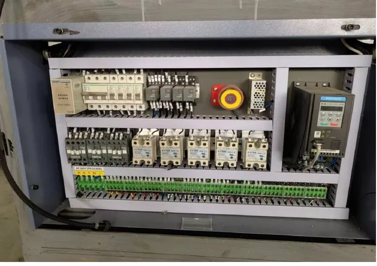
Decision matrix
| Inspection item | Evidence | Decision |
|---|---|---|
| Identity | Full code, VA rating, primary/secondary markings and diagram | Select the correct circuit and manual |
| Primary taps | Actual supply and installed link positions | Match the delivered transformer design |
| Secondary load | No-load/loaded voltage and connected circuit current | Find regulation loss or overload |
| Protection | Primary/secondary fuse or breaker identity | Preserve fault and conductor protection |
| Condition | Temperature trend, odor, noise, terminals and insulation evidence | Approve continued use or replacement |
Map both transformer circuits
Trace primary conductors, tap links, secondary conductors, grounding or bonding point and every protective device from the current schematic. List downstream coils, relays, power supplies, lamps and fans. Record recent additions because a new control load can exceed the original reserve or expose a weak connection.
Photograph nameplate and link layout before touching conductors. Transformers may provide multiple primary or secondary combinations; similar terminal numbers do not prove the same connection. If the schematic and installed links disagree, stop and resolve the machine configuration.
Measure supply and secondary behavior
Under the qualified live-test procedure, measure the primary at the transformer terminals and the secondary at both the transformer and a representative remote load. Record no-load, idle and active-cycle readings at the same time as current. A normal value with coils released can fall when several devices energize.
Compare readings with the installed component and machine documentation, not a universal percentage. The linked power-quality guide helps identify phase, feeder or facility variation before the transformer. Do not move a tap merely to hide voltage drop in a cable or terminal.
Inspect protection and connections
After isolation, inspect fuses, holders, breakers, terminals, ferrules and jumpers for heat, looseness, corrosion and wrong conductor placement. Identify fuse class and breaker characteristics as well as current marking. Never replace protection with a larger or slower device to keep the transformer energized.
Check that terminal hardware and conductor range match the device. Use the specified torque and keep primary and secondary wiring separation. Verify the intended protective-earth or secondary bonding arrangement from the drawing; informal bonding changes can create shock or signal problems.
Evaluate heat, sound and load cause
Record ambient and cabinet ventilation, operating duration, load state and temperature trend using an appropriate safe method. Abnormal hum may come from loose laminations, mounting, distorted supply or excessive load. Odor or discoloration is evidence to stop and investigate, not a reason to tighten an energized assembly.
Disconnect downstream branches only through an approved test plan. If secondary current falls and voltage recovers when one branch is isolated, inspect that circuit for overload or short. If regulation remains poor with a verified load, the transformer or its connections require component-specific review.
Validate replacement or correction
Match input range, taps, secondary voltage, VA capacity, frequency, isolation class, mounting, terminals, environment and protection. A physically larger transformer can change inrush and protection coordination. Document any approved substitution and update the drawing.
After work, restore barriers and run startup plus representative machine cycles. Confirm stable coil operation, secondary voltage, current and temperature trend. Send HANNAI the transformer label, tap photo, circuit reference and load measurements for compatibility review.
Technical references
- Siemens control power transformer product reference — general component guidance; the installed machine documentation remains controlling.
Related machine and guide
Review the HN-M100 automatic paper cup machine for machine context, then use the power quality and voltage imbalance guide for the adjacent check. Browse all Buyer Guides when building a wider project checklist.
Frequently asked questions
Can a tap be moved while the transformer is energized?
No. Isolate all windings and follow the exact transformer procedure.
Does correct no-load voltage prove the transformer is healthy?
No. Measure voltage and current with the real control loads energized.
Can a larger fuse stop repeated failures?
It can remove intended protection; investigate the circuit and use only the approved device.
What data is needed for a replacement?
Provide full nameplate, supply, tap layout, secondary loads, protection and mounting details.
Review your machine configuration with HANNAI
Send the machine model, project reference, component labels, drawings, photos and a description of the required result. We will clarify which details must be confirmed before a quotation or technical recommendation.