Paper cup machine foundation leveling and anchor-bolt inspection should preserve the machine’s installed geometry without treating every vibration as a loose anchor. Floor condition, support feet, shims, frame distortion, utility loads and connected equipment can all change the evidence. A reliable inspection compares defined reference points with the accepted installation baseline, then verifies machine motion and cup quality after any correction.
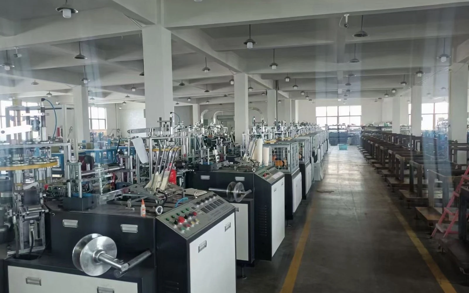
Start from the approved installation reference
Obtain the machine layout, lifting and foundation instructions, support-point drawing, utility plan and site-acceptance record. Identify whether the supplied model uses anchors, leveling feet, isolation pads, grout, a skid or another arrangement. Do not add anchors or copy a bolt pattern from a similar-looking machine.
The installation and startup checklist covers the complete commissioning scope. This guide focuses on the condition of the installed support after positioning, production or maintenance work.
Record the symptom before tightening anything
Useful observations include a new rocking motion, repeated fastener movement, changing station alignment, a gap under one foot, cracked grout, a shifted witness mark, abnormal vibration or a problem that began after relocation. Record the first event, machine state, product, speed stage and recent floor, utility or maintenance work.
Inspect from a safe distance during operation. Note whether movement follows a particular cycle event or starts when a compressor, collector or packing machine operates. A connected pipe, duct or conveyor can transmit force to the frame and make a support point appear to be the original source.
Build a foundation evidence table
| Observed condition | Evidence to collect | Diagnostic direction |
|---|---|---|
| One foot shows a visible gap | Reference point, shim pack, floor contact and frame condition | Confirm support loss without forcing the frame |
| Anchor witness mark moved | Bolt identity, joint surface, surrounding crack and event history | Separate joint movement from a disturbed mark |
| Vibration changed after relocation | Previous baseline, floor, level record and utility connections | Review installation geometry before machine timing |
| Repeated alignment drift | Station measurements, frame references, support and thermal state | Find whether the base reference is changing |
| Grout or floor is cracked | Crack map, load point, moisture and surrounding settlement evidence | Escalate structural assessment before retightening |
Inspect the floor and support path
Stop the machine through the approved sequence, apply lockout and verify isolation before reaching beneath or inside the frame. Control stored pneumatic, spring and gravity energy. Clean loose debris without removing shims or disturbing reference marks.
Inspect accessible floor areas, grout, pads, feet, shims, brackets and frame members. Look for corrosion, oil contamination, cracked support material, fretting dust, displaced shims, bent brackets or a foot that no longer carries load. Photograph each support using the same orientation and label it to the layout.
Measure level at defined references
Machine level is meaningful only when the instrument, reference surface, orientation and machine state are repeatable. Use the supplier-defined frame or bed locations and a suitable calibrated instrument. Record readings, environmental condition and whether connected utilities or equipment were attached.
Do not place a level on an unverified cover, guard or product guide. A local surface may not represent the machine base. Compare lengthwise, crosswise and any station-specific references required by the manual without inventing a universal tolerance.
Assess anchors without uncontrolled torque
Confirm anchor type, size, installation detail and supplier-approved tightening method. Visible looseness, corrosion, damaged threads, cracked concrete or a lifted base require investigation before torque is applied. A torque value copied from a general bolt chart may be wrong for the anchor, joint and substrate.
Qualified personnel should evaluate suspected structural damage or failed anchors. Do not drill new holes while utilities, embedded services or the machine base are unverified. If an anchor is meant to locate rather than distort the frame, excessive tightening can change station alignment.
Correct the cause in a controlled sequence
Remove external pipe or conveyor strain where identified, then follow the approved leveling and anchoring sequence. Support the machine safely before adjusting feet or shims. Use compatible, stable shims at documented locations; do not stack improvised scrap material under a precision support.
Recheck frame references after each approved adjustment. The coupling and shaft alignment guide is relevant when the support change affects a driven assembly. Foundation correction and shaft alignment must be coordinated rather than treated as unrelated tasks.
Verify motion and finished cups
After work, account for tools, restore guards and reconnect utilities without imposing unintended load. Follow the documented startup. Observe the machine at controlled stages and compare vibration, sound, anchor marks and support condition with the original evidence.
Inspect consecutive cups for dimensions, seam, bottom, rim, surface and stacking as applicable. A level frame is not a sufficient release result if tooling or transfer references changed during the work. Record final measurements, actions, first-off samples and responsible approval.
Frequently asked questions
Should every paper cup machine be anchored to the floor?
Not automatically. The required support and anchoring arrangement depends on the delivered model, floor and installation design. Follow the supplier drawing.
Can an anchor bolt simply be tightened when its mark moves?
No. First inspect the joint, threads, substrate, support and event history. Uncontrolled tightening can hide damage or distort the frame.
Does a level reading prove all machine stations are aligned?
No. It verifies defined base references. Station, shaft, tooling and transfer alignment may require separate checks after the base is stable.
What evidence should be sent for installation review?
Provide the machine model, layout, support and anchor photos, floor condition, labeled level readings, vibration symptom, connected-utility arrangement and recent changes.
Send the machine model, installation drawing, floor and support photos, labeled measurements, symptom history and first-off product evidence through our inquiry page. HANNAI can compare them with the delivered installation configuration.