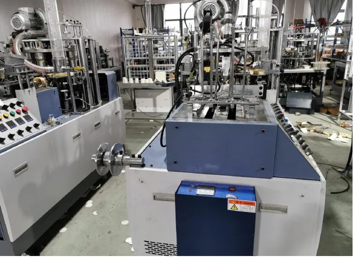
Paper cup machine I/O acceptance evidence connects the electrical drawing to what the machine actually observes and does. A green status on an HMI does not by itself prove the correct physical sensor or actuator is mapped to that label.
This guide defines an acceptance record, not an output-forcing procedure. Qualified personnel must choose and perform tests under the builder’s commissioning and isolation instructions. Safety-related signals require their applicable validation process.
Decision worksheet
| Signal record | Evidence to retain | Acceptance question |
|---|---|---|
| Identity | Device tag, drawing revision and logical name | Are physical and software identities linked? |
| Observed state | Approved stimulus and indicated response | Does the intended signal change correctly? |
| Sequence effect | Expected behavior and witnessed result | Does the process respond as specified? |
| Test closure | Temporary test removal and review | Is the machine restored for release? |
Create a signal list from the accepted drawings
Start with the current electrical and pneumatic documentation and the machine software signal list where available. Link physical device tags, terminal references, logical names and operator indications. Record the drawing revision used in the review. Resolve duplicate or unclear labels before testing.
Separate ordinary process signals from safety or protective functions. Identify connected-equipment interfaces such as ready, fault or transfer permissions without assuming their electrical characteristics. The supplier should confirm those interface details and the required acceptance method for the installed line configuration.
Define expected states and transitions
For each selected signal, describe the normal state, the approved test stimulus, the expected indication and the expected machine response. Include operating-mode context where it affects behavior. A signal may be correctly indicated while its consequence differs between setup and automatic operation.
Record state transitions instead of one static screenshot. For example, an approved material-presence check should identify both the change in indication and the permitted process response under the specified test conditions. Do not infer full sequence correctness from a single LED or an HMI label.
Use a qualified, controlled test method
Agree the test plan with the builder and qualified commissioning personnel. Determine when isolation, guarded observation or a supplier-approved simulation is required. Never reach into moving equipment, bypass a protective device or force outputs to complete a worksheet. This article provides no forcing commands or electrical connection values.
Where simulation is permitted, record exactly which part of the signal path was represented and which was not. A simulated input may test software response without proving physical sensor alignment or wiring integrity. Keep those limitations visible so the acceptance decision does not treat partial evidence as a complete physical test.
Record mismatches as defects to resolve
For a failed test, retain the signal identity, equipment state, stimulus, actual response and supporting observation. Identify whether the mismatch concerns labeling, wiring correspondence, indication, timing or sequence behavior. Avoid correcting a label informally while leaving the drawing and configuration record inconsistent.
For example, two adjacent sensors could appear in reverse logical positions. A documented mismatch lets the supplier assess the cause and prescribe the correction. After authorized work, repeat the affected test and any related checks required by the change assessment. Record the new result alongside the original finding.
Close temporary tests before production release
Qualified personnel should confirm removal of temporary simulation, test connections or other approved commissioning measures. Follow the builder’s return-to-service sequence, then perform the required machine and product checks. A checklist is not closed while a temporary test state remains unexplained.
Retain a signed matrix showing signal, expected response, actual result, reviewer and limitations. Update the drawing and software cross-reference after accepted changes. This matrix gives the buyer traceable evidence of what was checked, making later module replacement or fault investigation more reliable than relying on commissioning photographs alone.
Related equipment and next checks
Review the HN-M100 Automatic Paper Cup Machine and the related PLC I/O replacement and address mapping. The Engineering Notes archive connects these checks with wider machine planning.
Frequently asked questions
Does an HMI status prove the correct sensor is connected?
It proves a displayed state only. Establish the link through the approved physical and logical acceptance checks.
Can simulated inputs replace all onsite tests?
No. Record what the simulation covers and verify remaining physical functions through the approved method.
Should safety signals use the same worksheet alone?
They require the applicable qualified safety validation; a general process-signal checklist is insufficient.
What should be delivered at acceptance?
The signal matrix, drawing revision, observed results, corrected mismatches and closure of temporary test states.
Review the evidence with HANNAI
Send the machine serial number, accepted drawing revision and interface list. HANNAI can help clarify the machine-specific I/O acceptance evidence required for commissioning.