A centralized lubrication reservoir can remain full while one paper cup machine bearing, cam or slide receives too little lubricant. Pump operation, distributor condition, metering elements, branch lines and the final delivery point must all be verified. Increasing the system setting without locating a restricted branch may over-lubricate healthy points and leave the affected component unprotected.
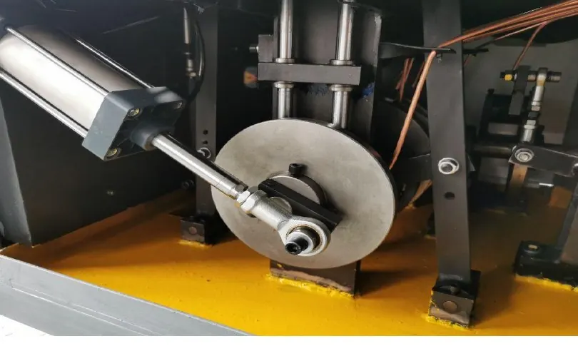
Map the complete distribution system
Start from the lubrication diagram and identify reservoir, approved lubricant, pump, controller or timer, pressure indication, filters, main line, distributors, metering units, branch tubing and each destination. Photograph tags and routes so a line cannot be reconnected to the wrong point.
The paper cup machine lubrication plan defines product and interval control. This guide narrows the work to proving delivery through a centralized or distributed system where fitted.
Recognize a delivery imbalance
Record new noise, heat, dry contact, abnormal wear, a low-level or pressure alarm, unexplained lubricant consumption, leakage or one branch that looks different from neighboring points. Note operating hours, speed, recent line repair, lubricant refill and ambient condition.
Do not approve delivery from external wetness alone. Lubricant around a fitting may be leakage or over-application and does not prove that the component working surface receives the correct amount.
Use a branch-delivery evidence table
| Observed condition | Evidence to compare | Diagnostic direction |
|---|---|---|
| Pump cycles but one point stays dry | Distributor outlet, metering element, branch line and endpoint | Trace the local restriction or disconnection |
| Pressure rises abnormally | Filter, main line, blocked branch and relief behavior | Look for downstream resistance |
| Lubricant appears at a fitting | Connection seating, tube damage, pressure and destination evidence | Separate leakage from intended delivery |
| One branch consumes too much | Metering identity, missing restriction, line routing and component seal | Verify branch control and compatibility |
| Fault follows lubricant refill | Product identity, contamination, air entry, viscosity and priming procedure | Review refill and product control |
Isolate movement and stored pressure
Apply lockout, verify electrical and mechanical isolation, and control pneumatic, spring and gravity energy before reaching a lubrication point near cams, chains or forming stations. Central systems can retain pressure after the pump stops; release it only through the documented procedure.
Never loosen a pressurized fitting to see whether lubricant sprays out. Protect paper paths and tooling from contamination, and use suitable eye, hand and spill protection for the approved lubricant.
Verify reservoir, pump and main-line condition
Confirm lubricant identity, level, cleanliness and refill record. Inspect reservoir seals, follower or agitator where fitted, pump command, alarms, filter and main-line connections. A pump sound does not prove it has primed or displaced lubricant.
Use the supplier’s test cycle and indication. Record the starting state, cycle duration or displacement evidence and pressure response only if those measurements are part of the approved method.
Inspect distributors and metering elements
Keep every outlet identified. Inspect distributor blocks, progressive elements or metering units for contamination, incorrect orientation, damage, mixed part identity or unauthorized adjustment. Components that look similar may deliver different quantities or operate by different principles.
Do not drill, enlarge or bypass a metering point. If removal is authorized, preserve port location, cleanliness and component identity, then follow the specified priming and air-removal method during reassembly.
Trace each branch to its destination
Inspect tubing for kinks, crushing, abrasion, heat exposure, tight bends, loose support and leakage. Confirm that each route ends at the intended bearing, guide, cam or slide and has not been swapped during maintenance. Pay attention to flexible sections that move every cycle.
At the endpoint, inspect the fitting, passage and component-side evidence. A clear tube may still terminate at a blocked internal passage, while a damaged bearing seal may lose lubricant before it reaches the working interface.
Connect delivery evidence to component condition
Compare neighboring points, but do not assume they require identical quantities. Record temperature, sound, visible contact pattern and wear according to the component method. Use the bearing condition monitoring guide when heat or noise initiated the inspection.
If a component has run dry, lubrication restoration alone may not return it to service. Qualified maintenance personnel must assess damage, clearance, alignment and replacement need.
Prove delivery without over-lubricating
After approved repair, restore lines, supports, guards and pressure protection. Run the documented lubrication test and verify the affected branch using the specified indicator, measured output or endpoint evidence. Do not repeatedly cycle the pump beyond the procedure.
Start production in controlled stages and monitor leakage, alarms, heat, noise and cup contamination. Record the exact branch, metering component, correction, lubricant and follow-up result for the next maintenance decision.
Frequently asked questions
Does a full reservoir mean every lubrication point is supplied?
No. Pump priming, distributors, metering elements, branch lines and internal passages can prevent delivery to one or more points.
Can system pressure be increased to clear a blocked branch?
Not without the supplier procedure. Excess pressure can damage tubing, seals, metering components or healthy branches and create injection hazards.
Should all branch lines show the same lubricant movement?
Not necessarily. Metered quantities, line dimensions and operating principles may differ. Compare each point with its documented requirement.
What records are useful after a blocked line?
Keep line and point identity, lubricant batch, pressure or cycle evidence, removed-component condition, repair method and component-side follow-up findings.
Send the machine model, lubrication diagram, lubricant identity, alarm history, branch photos under isolation and endpoint condition evidence through our inquiry page. HANNAI can review the supplied distribution arrangement.