A paper cup machine pneumatic system must deliver the correct air condition at the correct actuator during each machine cycle. When a cylinder moves slowly, a valve responds intermittently or pressure falls during production, effective troubleshooting follows the complete air path instead of increasing the regulator setting or replacing parts by guesswork.
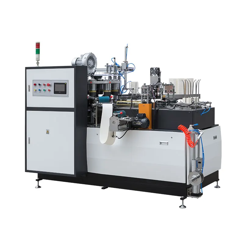
Define the on-machine pneumatic system boundary
Separate the factory utility from the machine circuit. The upstream compressor, receiver, dryer and distribution pipe provide the air supply. On the machine, the circuit may include an isolation device, filter-regulator-lubricator arrangement where specified, gauges, manifolds, solenoid valves, flow controls, cylinders, air nozzles, silencers and fittings. The installed arrangement depends on the supplied configuration.
The paper cup machine air compressor requirements guide covers utility planning. This article focuses on locating a fault after air reaches the machine connection.
Make stored-air safety the first control
Compressed air can move an actuator after electrical power is removed. Before opening a line, removing a valve or entering a guarded mechanism, follow the factory lockout procedure, isolate all relevant energy sources, vent stored pressure and verify the safe state. Consider gravity, springs and mechanisms that may move when pressure disappears.
Only qualified personnel should perform internal pneumatic or electrical checks. Never bypass a guard or interlock, hold a mechanism by hand, or search for a leak with skin. Use the approved leak-detection method and suitable personal protection.
Use a pneumatic troubleshooting evidence table
| Check point | Evidence to record | Decision question |
|---|---|---|
| Fault condition | Exact symptom, alarm, station, machine mode and cycle point | What expected movement or air function did not occur? |
| Machine inlet | Supply state, gauge reading and change from idle to cycling | Does usable air reach the machine under demand? |
| Air preparation | Filter condition, condensate, regulator state and flow direction | Is the air prepared and regulated as specified? |
| Control element | Valve command, indicator, manual state, exhaust and connector condition | Is the intended valve receiving and executing the command? |
| Actuator and load | Cylinder travel, speed, end position, leakage and mechanical resistance | Can the actuator move the mechanism without binding? |
| Release proof | Repeated cycles, pressure behavior, alarm status and cup result | Was stable operation demonstrated after the correction? |
Capture the event before changing a regulator
Record whether the problem appears at startup, only at normal production speed, after a long run, during a cup-format change, or when several actuators operate together. Note the first abnormal station, exact alarm, inlet and branch gauge behavior, sound, moisture evidence and any recent maintenance or utility change.
A short video that shows the HMI, gauge and affected movement from a safe position can be more useful than a general statement such as “air is unstable.” Organize the evidence with the remote troubleshooting evidence checklist before resetting alarms or disturbing the original condition.
Compare static pressure with real cycle demand
An acceptable reading while the machine is stopped does not prove adequate flow during production. Observe the approved gauge points through the actual cycle and determine whether the drop begins at the factory supply, machine inlet or one branch. A restricted pipe, closed valve, undersized connection, saturated filter or simultaneous demand elsewhere in the factory can produce a dynamic problem.
Do not compensate for a supply or restriction fault by raising pressure above the documented machine setting. Excess pressure can increase impact, leakage and component stress without correcting insufficient flow.
Inspect air preparation and distribution in sequence
Confirm the isolation valve is fully in its intended position and flow direction is correct. Inspect the filter bowl, element, drain, regulator, gauge and any specified lubricator according to the component instructions. Record condensate, contamination, cracked tubing, tight bends, rubbing, heat exposure, loose fittings and damaged silencers.
Automatic drains and filters can appear normal externally while flow is restricted or moisture is carried downstream. Do not introduce oil into a circuit unless the supplied documentation explicitly requires it; incompatible or excess lubricant can affect valves, seals and contamination control.
Separate the valve, actuator and mechanical load
A cylinder that does not reach position may be receiving no command, insufficient air, restricted exhaust or incorrect flow control. It may also have internal leakage, damaged seals, misalignment or a connected mechanism that binds. Confirm the permitted sequence and isolate these possibilities rather than immediately adjusting speed controls.
Compare the electrical command, valve indication, pressure at the relevant branch and physical movement. Exhaust silencers can restrict flow when contaminated, while a cylinder may pass a static check but lose force or speed under its real load. Component substitution should follow the exact porting, voltage, flow and function shown in the machine documentation.
Distinguish an air fault from a control-sequence fault
The pneumatic component can be healthy while the controller correctly prevents movement because a guard, sensor, drive-ready signal or previous station is not confirmed. Conversely, an output indication does not prove that the valve shifted or the actuator completed its stroke.
Compare the expected sequence with physical positions and controller indications. The sensor and interlock troubleshooting guide explains how to keep the command, input and mechanism evidence separate. Do not force PLC outputs or valve overrides during production.
Find leakage through controlled isolation
Check whether air loss is continuous or occurs only in one cycle stage. Under the approved procedure, isolate sections systematically and inspect fittings, tubing, valve exhausts, cylinder seals and manifolds with a suitable detection method. Record the location and machine state; a general factory leak and an actuator internal leak require different actions.
After repair, secure routing and fittings as designed, restore protection and verify the circuit at controlled speed. For equipment such as the HN-M100 automatic paper cup machine, final air settings and component details must follow the delivered machine rather than a generic online value.
Release the machine with repeated-cycle evidence
Restore guards, clear tools, account for personnel and follow the authorized restart sequence. Confirm stable inlet behavior, complete actuator travel, normal alarms and coordination with adjacent stations across repeated cycles before returning to the planned speed.
Inspect first-good cups and record the correction, replaced component identification and monitoring requirement. Pneumatic work can change timing or contact conditions even when the original symptom appears resolved.
Frequently asked questions
Does normal pressure at the machine inlet prove the pneumatic system is healthy?
No. The reading may change during cycling, and a restriction or leak may exist after the inlet. Compare approved gauge points under the same production condition and locate where the useful pressure or flow first becomes abnormal.
Should a slow cylinder be corrected by opening its flow control?
Not before preserving the setting and checking supply, exhaust, valve operation, cylinder condition, alignment and mechanical load. An unrecorded speed change can disturb the coordinated machine sequence.
Can a solenoid valve be judged only by its indicator light?
No. The light may show an electrical command, but it does not prove the spool shifted, air paths are clear or the actuator moved. Compare command, valve response, branch pressure and physical result.
When should the machine supplier be contacted?
Escalate when drawings are unclear, settings or overrides are undocumented, a fault affects coordinated timing, leakage is internal to a critical assembly, or the factory cannot demonstrate a safe and repeatable recovery.
Send the machine model and configuration, exact alarm, air-circuit reference, inlet and branch observations, affected actuator, safe video and recent changes through our inquiry page. HANNAI can review the available evidence and discuss the next configuration-dependent check.