A valve terminal or manifold can combine supply, exhaust, working ports, blanking plates, pressure zones and electrical addressing in one assembly. A physically similar replacement may route air or assign outputs differently, causing unexpected actuator motion.
Replacement begins with a verified port-and-function map. Depressurize stored pneumatic energy, isolate electrical power and support any actuator that could move under gravity. Never use manual overrides until the affected mechanism and safe direction are understood.
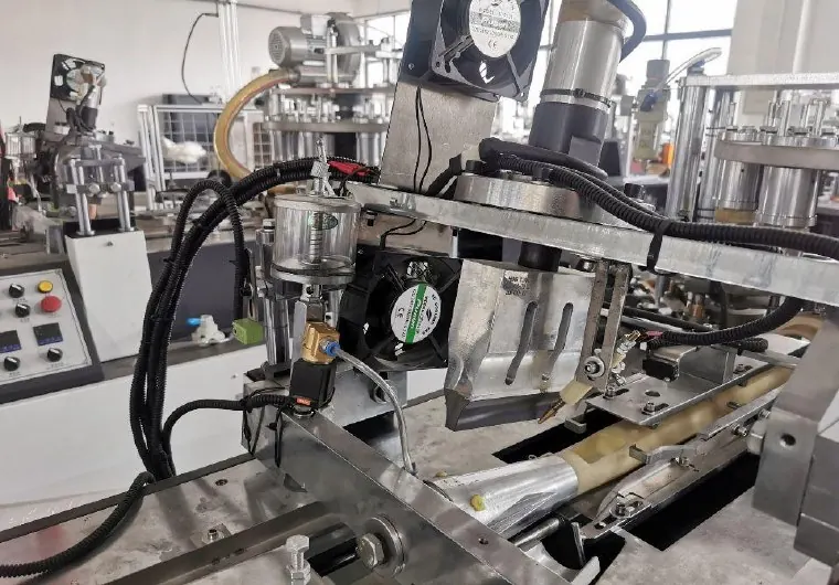
Decision matrix
| Mapping item | Evidence | Failure prevented |
|---|---|---|
| Station order | Valve position and controlled actuator | Stops output-to-actuator swaps |
| Pneumatic ports | Supply, exhaust and working-port labels | Prevents incorrect flow paths |
| Valve function | 3/2, 5/2, 5/3 and normal state as applicable | Preserves rest and fault behavior |
| Electrical interface | Voltage, connector, fieldbus node and output address | Preserves PLC command mapping |
| Manifold construction | Pressure zones, seals, plates and exhaust treatment | Prevents internal leakage or cross-pressure |
Build the as-installed map
Label each tube at both ends before disconnection. Photograph port numbers, valve station order, coil codes, manual overrides, supply entries, silencers and blanking plates. From the PLC I/O list, map each solenoid output to the actuator function and safe rest position.
Do not treat tube color as the primary identifier. Trace working ports to the cylinder or vacuum device and record which chamber is pressurized in each state. Compare the machine pneumatic drawing with the actual assembly and resolve discrepancies before removal.
Match manifold and valve construction
Festo valve-terminal documentation illustrates that seals, sub-bases, port patterns and pressure-zone arrangements are assembly-specific. Match the exact family, station width, valve function, flow direction, pressure range and permitted media from manufacturer data.
Confirm whether stations use single or double solenoids and how a valve behaves when electrical power is removed. A different center condition on a multi-position valve can release, trap or pressurize an actuator differently. Safety functions require the approved architecture and validation.
Match the electrical node and addressing
Record coil voltage, suppression and connector pinout for individually wired assemblies. For fieldbus or remote-I/O terminals, back up node configuration, station order, module types, address mapping and diagnostic settings. A mechanically correct terminal can still command the wrong station if module order differs.
Compare PLC outputs offline and inspect the replacement node configuration before applying air. Do not change the program merely to accommodate undocumented station swaps. If the exact product is obsolete, the conversion should have an approved mapping, drawing revision and rollback plan.
Assemble cleanly and test progressively
Keep open ports and tubes protected from contamination. Use the specified seals, fasteners and assembly sequence; avoid excess thread sealant that can enter passages. Confirm supply and exhaust connections, silencer condition and tubing bend radius.
First perform the permitted leak and communication checks with motion controlled. Then test one output at a time in setup mode, observing PLC command, valve indicator and actuator direction together. Restore guards and complete slow cycles before increasing speed. Stop for unexpected motion or pressure.
Record the final functional map
Update the port map, electrical address list, part numbers, pressure zones and photos. Store removed components with fault labels until the root cause is confirmed. Record any changed connector or tubing identification at the machine.
Send HANNAI the machine model, manifold label, full assembly photos, port map, I/O list and failure evidence for compatibility review. The linked valve-response guide helps determine whether the original fault belongs to the coil, spool, wiring or air supply.
Technical references
- Festo valve terminal support documentation — general component guidance; the installed machine documentation remains controlling.
Related machine and guide
Review the HN-180 high-speed paper cup machine for machine context, then use the solenoid valve response guide for the adjacent check. Browse all Buyer Guides when building a wider project checklist.
Frequently asked questions
Can a valve with the same connector replace the original?
Not without matching valve function, flow, pressure, normal state, manifold fit, voltage and addressing.
Why label tubes at both ends?
It preserves the working-port relationship when several similar tubes enter one manifold.
Can manual overrides be used for quick testing?
Only under the machine safe setup procedure after the actuator, direction and hazards are understood.
What proves a manifold conversion is controlled?
An approved port and I/O map, drawings, clean installation, leak checks and one-function-at-a-time cycle evidence.
Review your machine configuration with HANNAI
Send the machine model, project reference, component labels, drawings, photos and a description of the required result. We will clarify which details must be confirmed before a quotation or technical recommendation.