A sensor with the same body size can still be electrically or functionally incompatible with a paper cup machine. An incorrect output type may leave the PLC input permanently on, reverse the expected logic or damage a circuit. Replacement therefore starts with the machine drawing, the installed part number and measured operating evidence—not with appearance alone.
This checklist is for maintenance planning on conventional position, proximity and photoelectric sensors. Safety interlocks, guard switches and safety-rated devices require an approved equivalent and a qualified safety review; they should never be bypassed to keep production running.
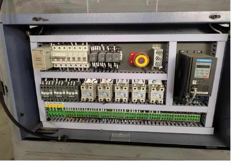
Decision matrix
| Compatibility item | Evidence to record | Why it matters |
|---|---|---|
| Sensing principle | Photoelectric, inductive, capacitive or mechanical | The target and environment determine what can be detected |
| Electrical output | PNP or NPN; NO, NC or selectable | The PLC input circuit and program expect a specific signal |
| Supply and load | Rated voltage, current and residual/leakage limits | A sensor may light its LED yet fail to drive the input correctly |
| Connection | Wire count, pinout, connector key and cable length | Matching colors or connector shells alone is insufficient |
| Mechanical fit | Thread, bracket, flush mounting and sensing distance | Position changes can create missed or double detections |
Identify the function before removing the sensor
Photograph the target, bracket, cable route, indicator state and PLC input while the machine is stopped in a known position. Label whether the device confirms cup blank presence, bottom-disc arrival, cylinder end position or another event. Record the exact alarm and the sequence step that is waiting for the signal.
Do not assume a failed input proves a failed sensor. First check target position, contamination, loosened brackets, cable damage, connector seating and the input terminal. A known metal target is useful for an inductive sensor; the actual paper or printed mark must be used for a photoelectric device.
Match the electrical interface
Read the part-number data sheet and the machine schematic together. Match DC or AC supply, two-wire or three-wire connection, PNP or NPN output and normally-open or normally-closed operation. Omron documentation treats PNP/NPN and NO/NC as separate output decisions; both therefore belong on the replacement record.
Where connectors are used, compare the pin assignment rather than the cable colors. Check whether the PLC input common is wired for sourcing or sinking signals. Any live electrical measurement should be made by a qualified technician using the machine manufacturer’s safe isolation and test procedure.
Match sensing and mounting behavior
For proximity sensors, compare nominal sensing distance, shielded or non-shielded installation, target material and the influence of surrounding metal. For photoelectric sensors, compare background suppression, light-on or dark-on logic, spot position, response and teach method. A longer nominal range is not automatically safer.
Recreate the original bracket datum before adjusting sensitivity. The replacement must detect the intended target across normal mechanical tolerance without detecting neighboring tooling, reflections or scrap. Keep the cable protected from sharp edges, heat and repeated flexing beyond its intended use.
Commission with a controlled sequence test
With guards restored, run the machine in the permitted setup mode and observe sensor LED, PLC input, HMI sequence and physical target together. Test several slow cycles before controlled production speed. Verify both arrival and departure of the target so a latched signal does not hide a fault.
Record the final part number, parameters, bracket position and connector pinout. Retain the removed sensor with a fault label until the root cause is confirmed. This makes the next replacement a controlled spare-parts decision rather than another emergency substitution.
Build a replacement approval record
The approval sheet should include the original and proposed part numbers, data sheets, electrical drawing reference, sensor function, test results and approver. For exported equipment, record local availability without changing the circuit design silently.
For a broader electrical baseline, pair this checklist with the linked alignment guide and the machine documentation supplied for the specific configuration. HANNAI can review photos, drawings and part numbers when preparing a machine or spare-parts discussion.
Technical references
- Omron proximity sensor terminology — used for the general component principle; the installed machine documentation remains controlling.
Related machine and guide
Review the HN-M100 automatic paper cup machine for machine context, then use the photoelectric sensor alignment guide for the adjacent maintenance or process check. Browse all Buyer Guides when building a wider project checklist.
Frequently asked questions
Can a PNP sensor replace an NPN sensor?
Not as a like-for-like change. The PLC input common and signal logic must support the output type; otherwise the circuit may not operate correctly.
Is the same connector enough to prove compatibility?
No. Confirm the connector key, pin assignment, supply, output circuit and logic from the data sheet and schematic.
Can sensitivity adjustment solve every missed detection?
No. Target position, sensing principle, contamination, mounting and wiring should be checked before changing sensitivity.
What information should be sent to the machine supplier?
Send the machine model, serial or project reference, sensor part number, clear installation photos, schematic reference, alarm and PLC input evidence.
Review your machine configuration with HANNAI
Send the machine model, cup or material drawings, component labels, photos and a description of the required result. We will clarify which details must be confirmed before a quotation or technical recommendation.