A thermal or electronic overload relay protects a motor circuit from sustained overload and certain phase faults. Resetting it without recording current and load can return a stalled, single-phased or mechanically bound motor to service. Automatic reset can also create an unexpected restart if the control circuit is not designed correctly.
The relay setting must be based on the approved motor and starter design, not adjusted until trips disappear. Qualified personnel should preserve the trip indication, isolate energy and review the exact relay characteristic and machine risk assessment before testing.
Decision matrix
| Evidence item | Record | Why it matters |
|---|---|---|
| Motor | Nameplate, connection, driven mechanism and duty | Defines approved current and application |
| Relay | Full code, range, setting, trip class and reset mode | Defines protection behavior |
| Trip event | Machine state, duration, phase currents and alarms | Links protection to actual load |
| Mechanical path | Binding, belt/chain, bearings and product jam | Finds non-electrical overload |
| Restart | Cooling, manual command, direction and current trend | Prevents unsafe repeat operation |
Preserve the trip state
Record relay indicator, contactor state, drive alarm, motor temperature and the exact sequence event. Note whether the trip followed startup, a jam, warm running or repeated stops. Do not reset before confirming the mechanism is safe and collecting the state that may disappear.
Identify whether the device uses thermal elements, current transformers, phase-failure logic or a thermistor input. The full part number controls what its display and contacts mean. A downstream motor fault and an incorrect relay setting can produce the same trip indication.
Compare setting with motor evidence
Read motor nameplate voltage, current, frequency, connection and duty, then confirm actual terminal connection and starter arrangement. Record relay range, dial setting and trip class without changing them. The setting relationship depends on direct-on-line, star-delta or other circuit design.
Siemens documentation treats rated operational current, trip class and reset behavior as separate parameters. Do not copy a setting from another motor of similar power. The linked motor checklist helps verify shaft, brake, fan and connection compatibility.
Measure all phases under controlled load
After inspection and only when safe to energize, record current in every phase during acceleration and representative running. Compare imbalance, duration and machine load. Check supply voltage and contactor contacts if one phase is low or missing.
A normal average current can hide one overloaded phase. Conversely, a brief starting peak should be interpreted through the approved protection curve, not assumed to be a fault. Stop on abnormal noise, slow acceleration, smoke or rapid heating.
Inspect the driven mechanism
With all energy isolated, check the motor, coupling, belt or chain, gearbox, bearings and process station for binding or accumulated material. Separate the motor from the load only through the machine procedure, especially where gravity, springs or stored pneumatic energy can move parts.
Resolve the mechanical cause before increasing the relay setting. A recurring jam may be created by tooling alignment, product feed or lubrication rather than the motor itself. Keep removed guards and interlocks in their designed condition.
Control reset and prove recovery
Siemens warns that automatic reset can allow immediate restart when a command remains present. Confirm the intended manual/automatic reset mode and that a new start command is required by the machine design. Wait for the device-specific recovery condition.
Run staged tests while monitoring phase current, acceleration, relay status and product load. Record the trip cause and correction. Send HANNAI the motor/relay labels, settings, current traces and mechanism photos before changing protection or replacing the starter.
Technical references
- Siemens SIRIUS overload relay manual — general component guidance; the installed machine documentation remains controlling.
Related machine and guide
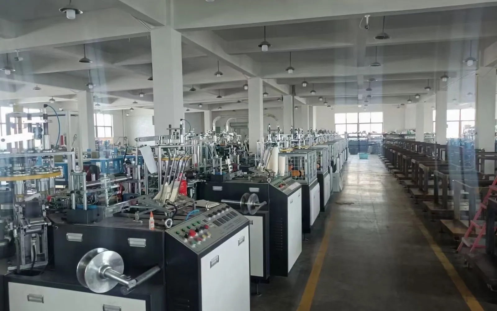
Review the HN-SF160 high-speed paper cup machine for machine context, then use the motor replacement checklist for the adjacent check. Browse all Buyer Guides when building a wider project checklist.
Frequently asked questions
Can the current setting be raised until trips stop?
No. Verify the motor, circuit and mechanical load against the approved design.
Is automatic reset always acceptable?
No. It can create unexpected restart and must match the machine safety/control design.
Why measure every phase?
A missing or imbalanced phase can be hidden by one overall observation.
What should be checked before reset?
Preserve the trip state, isolate hazards and inspect the motor and driven mechanism.
Review your machine configuration with HANNAI
Send the machine model, project reference, component labels, drawings, photos and a description of the required result. We will clarify which details must be confirmed before a quotation or technical recommendation.