Paper cup machine timing belt and pulley wear can change motion before the belt breaks. Tooth damage, edge wear, rubber dust, tracking marks or a changing phase relationship may point to misalignment, incorrect tension, contamination, bearing movement or an overloaded mechanism. Inspection should preserve timing references and find the cause instead of replacing only the visible belt.
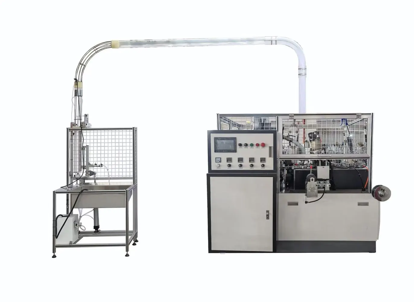
Confirm where synchronous belts are used
Review the machine drive and parts diagrams to identify each timing belt, driver, driven pulley, idler or tensioner, guard and timing reference. Do not assume a visible toothed belt drives the same station as an observed defect. Record the belt designation and installed orientation from approved documentation.
The chain, cam and drive timing guide covers the overall sequence. This article narrows the work to synchronous belt transmission and its pulley interfaces.
Capture symptoms without removing the guard
From outside the protected area, record noise, vibration, dust visible near the guard, changing station position, intermittent sensor timing or a fault that follows acceleration. Note when it began, product, speed stage, runtime and recent belt, bearing or changeover work.
Do not run with a guard removed to watch belt tracking. A slow-motion video from a safe external view may connect the product defect to a cycle event, but belt condition must be inspected after isolation.
Use a belt-condition evidence table
| Observed condition | Evidence to inspect | Diagnostic direction |
|---|---|---|
| Wear concentrated on one edge | Pulley alignment, flange contact, shaft support and guard rub | Find the side force causing tracking |
| Teeth damaged at repeated area | Pulley tooth condition, jam history, phase marks and local belt section | Review shock load or damaged engagement |
| Rubber dust inside guard | Belt surfaces, pulley grooves, contamination and nearby contact | Locate abrasion rather than cleaning dust alone |
| Belt appears polished or cracked | Material age record, heat, oil exposure, tension and pulley condition | Separate environmental damage from normal service |
| Timing changes after replacement | Part identity, tooth count, installation marks and tension method | Confirm compatible parts and phase setup |
Inspect under full isolation
Apply lockout, verify isolation and control stored spring, pneumatic and gravity energy before removing a belt guard. Prevent unexpected rotation. Photograph timing marks, belt direction, tensioner position and pulley relationship before loosening any component.
Inspect both belt faces, teeth, edges and splice-free continuous surface as applicable. Look for cuts, glazing, cracks, missing tooth material, oil, heat marks, embedded particles or a section with different tension. Inspect the complete circumference safely through the approved manual positioning method.
Check pulleys and supporting components
Clean only with a compatible method. Inspect pulley teeth, grooves, flanges, key or locking elements, fasteners, shaft condition, idlers and tensioner bearings. A worn or contaminated pulley can quickly damage a replacement belt.
Check runout, alignment, bearing play and mounting condition using the supplier’s references and calibrated tools. Do not lever a pulley into line or add unapproved washers. Correct the support cause while preserving the designed shaft and station relationship. Use the fastener and torque-mark inspection guide when pulley, tensioner or bearing-support movement is suspected.
Verify tension by the specified method
Belt tension may be established by deflection, frequency, tensioner position or another documented method. Use the exact belt span, machine state and supplier instruction. “Feels tight” is not a controlled measurement, and a universal number from another belt is unsafe.
Excess tension can overload bearings and shafts; insufficient tension can permit tooth jump, vibration or poor engagement. Record the tool, measurement location, value and acceptable reference. Recheck after pulley or bearing work because geometry may have changed.
Replace without losing machine phase
Confirm belt profile, pitch, width, length, material and supplier-approved part. Preserve timing marks and station position according to the manual. If more than one belt shares a drive or should be serviced as a set, follow the specified replacement scope.
Do not rotate one timed shaft independently unless the procedure allows it. Qualified maintenance personnel should install without prying or twisting the belt over a flange, set tension, secure fasteners and manually verify the cycle through the approved method.
Prove timing and product after service
Account for tools, reinstall guards and follow the documented restart. Observe external motion at controlled stages and confirm alarms, home or reference behavior and repeated cycle position. Stop if noise, dust or tracking evidence returns.
Run labeled cups and inspect the stations influenced by the drive. Check seam, bottom, rim, transfer and stacking as relevant. Record belt and pulley identity, measured condition, timing references, tension evidence and first-off results for future trend comparison.
Frequently asked questions
Can belt tension be checked by pressing it with a finger?
Not as a controlled acceptance method. Use the belt and machine supplier’s specified tool, span and procedure.
Does edge wear mean the belt is too loose?
Not necessarily. Misalignment, flange contact, pulley runout, bearing movement or guard contact can create edge wear.
Should only the belt be replaced when teeth are damaged?
Inspect the pulleys, tensioner, support, jam history and phase. A damaged interface or overload can quickly harm the new belt.
What should be sent for timing-belt diagnosis?
Provide machine and belt identity, full-circumference photos, pulley and edge evidence, timing marks, tension method, fault sequence and recent work.
Send the machine model, belt and pulley identification, condition photos under isolation, timing references, tension evidence and affected product samples through our inquiry page. HANNAI can review the drive relationship for the supplied configuration.