Roll die cutting machine rotary-tool inspection should distinguish a damaged cutting edge from incorrect mounting, contaminated interfaces, material variation and anvil support. Flexible dies, solid rotary tools and other supplied constructions have different handling rules, but all require controlled identity, clean seating, protected edges and mapped blank evidence before production release.
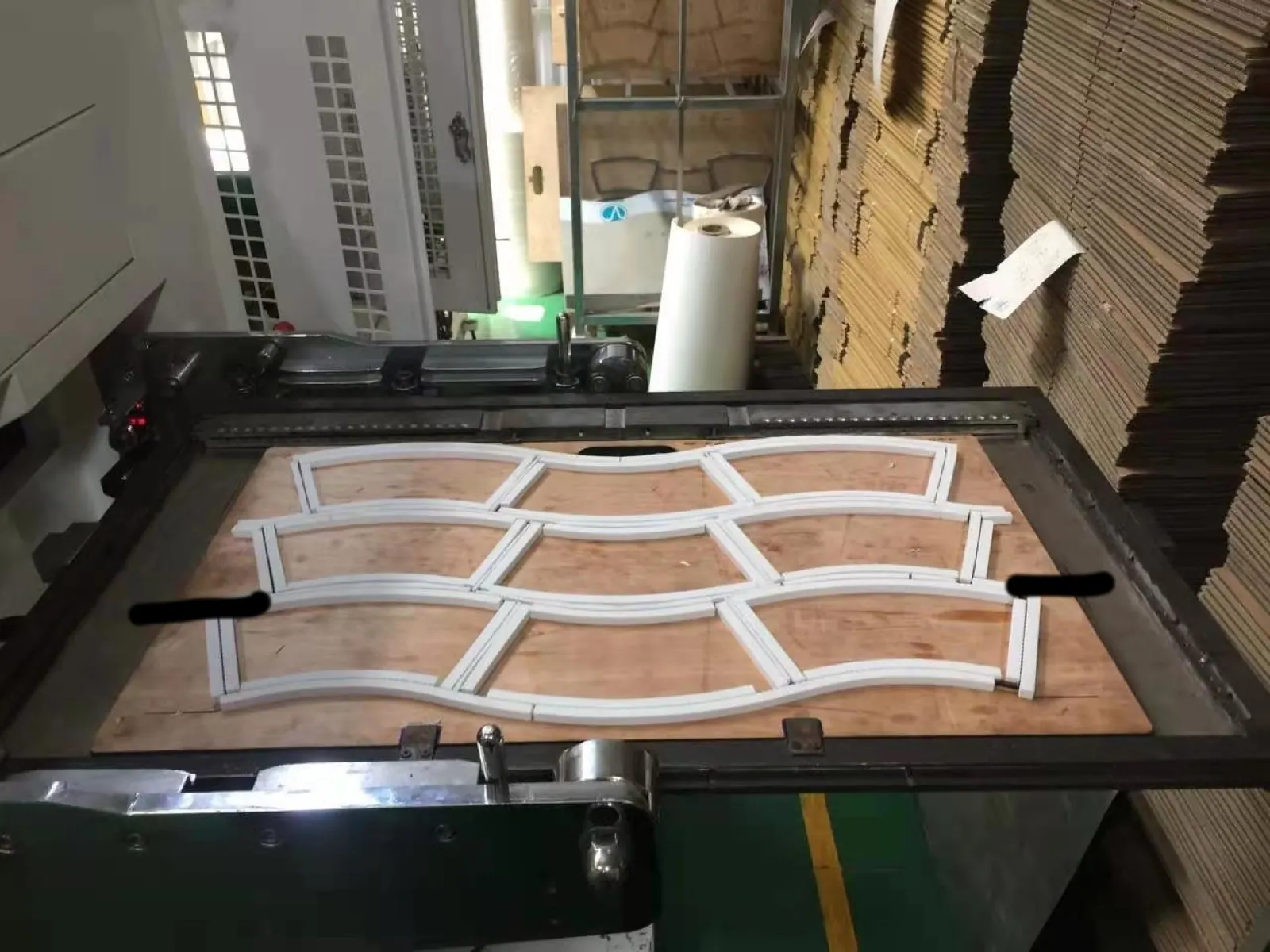
Identify the exact rotary tool construction
Record machine model, tool drawing, tool or die number, cutting pattern, repeat, working width, material specification, approved rotation direction and whether the delivered system uses a flexible die, solid cylinder or another construction. Confirm lifting, storage and mounting instructions before handling.
The cutting pressure and die alignment guide covers process setup. This article focuses on physical tool-edge and mounting evidence before pressure is changed.
Build a repeat-defect map
Collect consecutive blanks and mark machine direction, cross-machine position and repeat number. Separate incomplete cut, crushed edge, burr, fibre pull, nick, double line, changing registration or marking outside the cut. Preserve both accepted and defective samples from the same material roll.
A defect that repeats at the same tool position points in a different direction from one that moves with web tension or material splice. Do not increase pressure before the location is mapped.
Use a rotary-tool evidence table
| Observed pattern | Evidence to inspect | Diagnostic direction |
|---|---|---|
| Incomplete cut repeats at one feature | Mapped tool edge, local contamination, material and anvil position | Inspect the specific cutting geometry |
| Cut changes after tool installation | Tool identity, seating surface, mounting sequence and reference marks | Verify installation before process pressure |
| Edge damage appears near one end | Handling record, protective cover, storage and mounting contact | Review impact or unsupported handling |
| Cut varies across machine width | Tool seating, runout evidence, bearings, anvil and material thickness | Separate global geometry from a local nick |
| New tool marks the substrate | Tool specification, clearance, debris, pressure and approved sample | Confirm compatibility and setup boundary |
Stop, isolate and control heavy tooling
Apply lockout and verify electrical, pneumatic, hydraulic and rotational isolation. Prevent cylinder movement and use the specified lifting and blocking equipment. Cutting edges remain hazardous when stationary, and rotary cylinders or magnetic tools may be heavy or strongly retained.
Wear the protective equipment specified by the tool manufacturer. Never place an unprotected edge on a bench, use the cutting rule as a lifting point or leave a tool where it can roll.
Inspect the cutting edge without altering it
Clean by the approved method and use safe magnification or lighting where required. Inspect for nicks, rolled or flattened areas, corrosion, adhesive, embedded fibre, coating transfer, cracked bridges or other construction-specific damage. Keep findings referenced to the blank defect map.
Do not file, grind or stone an edge unless the tool supplier has approved a repair method. Informal reshaping changes geometry and can create a larger pressure or safety problem.
Inspect mounting and seating surfaces
Check the cylinder, magnetic surface, shell, bearer, locating features, keys, fasteners and interfaces applicable to the delivered tool. Look for debris, burrs, corrosion, raised damage, trapped labels or uneven contact that can prevent repeatable seating.
For flexible dies, inspect retention and orientation according to the supplied sequence. For solid tools, verify supports, lifting points and locking devices. Do not mix fasteners, shims or mounting practices from another tool system.
Preserve reference, phase and rotation direction
Photograph reference marks before removal. Confirm tool rotation, web direction, registration feature and cylinder phase from the approved setup record. A tool can be mechanically secure but installed in the wrong orientation or reference position.
Qualified personnel should use the specified tightening pattern and tooling. Record fastener condition and final verification rather than relying on a visual check alone.
Separate tool-edge evidence from anvil condition
A sound tool can produce a poor cut over a damaged or contaminated support surface. Compare the defect position with the anvil surface inspection guide. Material thickness and compressibility also affect the result.
Do not compensate for one local defect with a machine-wide pressure increase. That can overload healthy tool sections, shorten tool life and mark the substrate.
Prove the tool with controlled blanks
Restore guards, account for tools and follow the documented startup. Run a defined sample at controlled speed and inspect every critical feature using the agreed cut-quality method. Keep machine- and cross-direction orientation visible.
Increase production only after repeat, registration, cutting consistency, waste separation and blank condition remain stable. Record tool identity, mounting date, material lot, mapped result and any authorized correction.
Frequently asked questions
Should cutting pressure be increased when one feature does not cut?
Not before the local edge, mounting, anvil position and material are inspected. A global increase can damage healthy areas.
Can a rotary cutting edge be sharpened by hand?
Only if the specific tool supplier provides an approved repair method. Informal filing or grinding changes geometry and safety.
Does a new tool eliminate the need for incoming inspection?
No. Confirm identity, shipping condition, edge protection, mounting surfaces, direction and the approved first-off blank.
What evidence helps a tool supplier investigate?
Provide tool and machine identity, repeat-defect map, oriented blanks, isolated edge and mounting photos, material data and the setup record.
Send the machine and tool identity, oriented blank samples, defect map, isolated tool-edge and mounting photos, material specification and setup record through our inquiry page. HANNAI can review the evidence boundary for the supplied system.