Paper cup machine vacuum pickup faults can appear as missed blanks, intermittent feeding, double pickup, late release or unstable transfer. A reliable diagnosis follows the negative-pressure path, pickup surface, material presentation, control command and machine timing instead of treating every missed feed as a weak-vacuum problem.
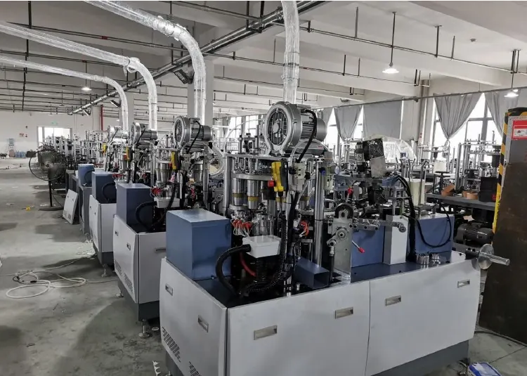
Map the vacuum function before diagnosing it
Identify what the vacuum circuit is intended to pick, hold, transfer and release. Depending on the machine configuration, negative pressure may be produced by a venturi device or another supplied source and routed through valves, filters, hoses, manifolds and suction elements. Confirm the actual arrangement from the pneumatic drawing and parts documentation.
Keep this circuit separate from positive-pressure functions such as cylinders and air nozzles. A normal factory air supply does not prove the vacuum generator, filter, hose or pickup point is working correctly.
Control movement and stored energy before inspection
Pickup mechanisms can move quickly and may retain pneumatic, spring, gravity or mechanical energy after a stop. Follow the authorized lockout procedure, isolate and vent the relevant supplies, verify a safe state and prevent suspended or spring-loaded parts from moving before reaching into the feed path.
Only qualified personnel should open pneumatic or electrical assemblies, command outputs or measure internal circuits. Never bypass a guard, hold material near a moving pickup, or place fingers over a suction point during a production cycle.
Use a vacuum pickup evidence table
| Check point | Evidence to record | Decision question |
|---|---|---|
| Material presentation | Blank identity, stack height, flatness, orientation and surface condition | Is one suitable blank consistently available to the pickup? |
| Pickup contact | Suction element condition, contact position and visible sealing area | Can the pickup form and maintain an effective seal? |
| Vacuum path | Source state, filter, hose, fittings, manifold and measured behavior | Where does negative pressure first become weak or unstable? |
| Command timing | Valve indication, pickup-on, transfer and release sequence | Does vacuum occur at the required point in the cycle? |
| Transfer movement | Arm or gripper path, vibration, obstruction and release position | Is the material lost because of motion rather than vacuum? |
| Recovery proof | Repeated pickups, speed condition, alarms and first-good cups | Is feeding stable without creating a new defect? |
Preserve the exact pickup failure
Record whether the machine picks no blank, loses it during transfer, lifts two blanks, releases late or fails only at a particular speed. Note the material lot, stack condition, machine mode, alarm, cycle position, surrounding sound and any recent cleaning, changeover or pneumatic work.
Capture safe slow-motion video when permitted, including the pickup point and the next transfer step. The remote troubleshooting evidence checklist helps connect the visible event with the alarm and machine configuration.
Confirm material presentation before changing vacuum
Fan blanks that are curled, damaged, stuck together, incorrectly oriented or poorly supported may not present a repeatable surface. Paper dust, coating condition, static behavior, print build and stack compression can change separation. Compare the affected stack with approved material and a known acceptable batch.
The sidewall fan blank inspection and feeding guide defines the upstream checks. Correcting an unsuitable stack by increasing vacuum can worsen double pickup or hide a material-handling issue.
Inspect suction elements and the sealing surface
Under safe isolation, inspect suction cups, pads or other pickup elements for wear, hardening, cuts, contamination, deformation and loose mounting. Confirm that contact position and approach angle match the controlled machine reference. A sound component can still leak if it contacts an edge, printed relief, damaged blank or uneven stack.
Use only compatible replacement parts with the specified material, geometry and connection. A visually similar suction element can have different compliance, flow or release behavior and may change the feeding sequence.
Trace the negative-pressure path to the source
Inspect filters, hoses, connectors, manifolds and valve paths for contamination, collapse, sharp bends, abrasion, loose fittings or internal restriction. If the system uses compressed air to generate vacuum, also confirm that usable supply remains available during the pickup event, not only while the machine is idle.
Measure only at approved points with suitable instruments and the documented method. Compare results under the same material, speed and cycle condition. A single unloaded reading at the source may not reveal leakage or restriction near the pickup.
Separate vacuum level from command and release timing
The pickup can fail even when adequate vacuum is available if the control valve turns on late, releases early or retains vacuum beyond the handoff. Compare the HMI or output indication, valve response, physical pickup and release position in sequence. The sensor and interlock guide can help determine whether the expected material or position signal is missing.
Do not force an output or extend a timer without supplier-approved evidence. A timing change may affect grippers, transfer arms, sealing position or another coordinated station.
Check transfer motion before blaming the pickup
A blank may be acquired correctly and then lost because of vibration, sudden acceleration, misaligned guides, contact with an obstruction or incorrect handoff position. Follow the blank from first contact through release and identify where control is first lost.
The final feed and transfer arrangement depends on the delivered machine, supplied tooling, material and project. Use the specific machine documentation rather than copying another model’s pickup location, timing or setting.
Prove recovery with an approved material sample
After authorized work, restore guards and protection, clear tools and follow the documented restart sequence. Observe repeated pickups at the permitted test condition before returning to planned production. Check for missed feed, double feed, late release, blank damage and downstream cup defects.
Retain first-good samples and record the material lot, machine setting reference, correction and monitoring result. Use the pre-production sample approval checklist when the fault occurred during a new material or cup setup.
Frequently asked questions
Does a missed blank always mean the vacuum level is too low?
No. Blank presentation, suction contact, leakage, restriction, command timing, transfer motion and detection can create the same visible symptom. Identify where the pickup sequence first fails.
Should vacuum be increased when two blanks are picked together?
Not automatically. Preserve the current setting and inspect blank separation, stack condition, static behavior, pickup contact and timing. Increasing vacuum may make double pickup more frequent.
Can a suction cup be reused if it has no obvious tear?
Visual condition is only one check. Hardening, deformation, contamination, loss of compliance or incorrect mounting can reduce sealing and release performance. Follow the component inspection and replacement criteria.
When is supplier support appropriate?
Request support when the vacuum circuit is undocumented, timing changes appear necessary, pickup references have moved, repeated failures remain after controlled checks, or safe verification requires access beyond the factory’s authorization.
Send the paper cup machine model, supplied configuration, blank specification, exact pickup symptom, alarm history, safe cycle video and recent changes through our inquiry page. HANNAI can review the evidence and discuss the next controlled check.