Roll die cutting machine reel loading and unwinding preparation determines whether printed paper enters the cutting section with a stable edge, correct orientation and controlled tension. A damaged reel, wrong shaft support, poor centering or careless splice can create register drift, web breaks and waste that later look like die or servo problems. Preparation should therefore be treated as a documented production step.
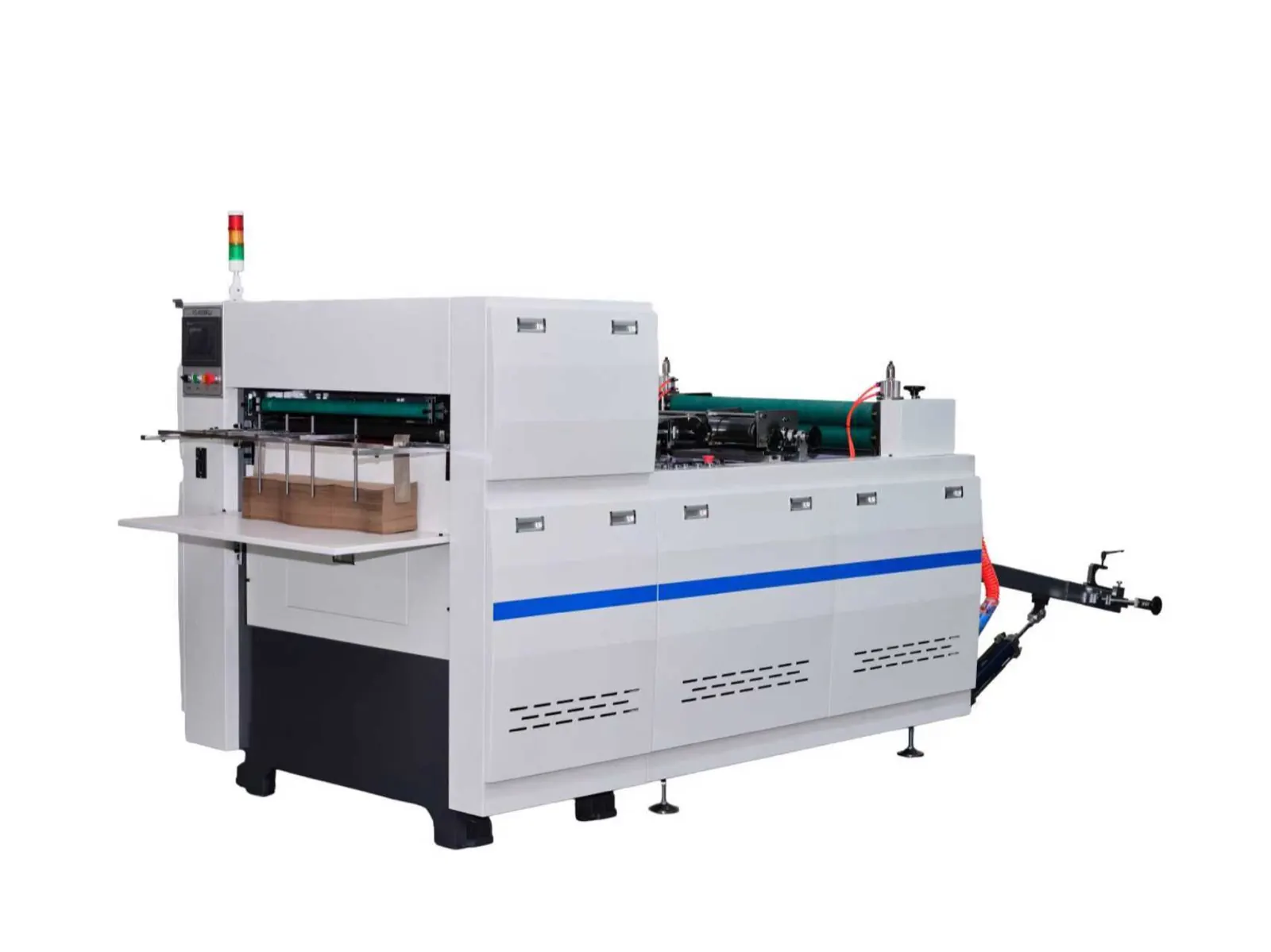
Confirm reel and layout identity before lifting
Match the material label with the production order, artwork version, coating side, roll width, paper specification, print direction and die layout. Record reel identification and visible condition. A correctly loaded but wrong revision can produce a complete roll of unusable blanks.
Use the printing artwork and registration checklist to verify marks and orientation. Confirm which edge and printed reference the machine uses. Do not assume the outside face of one reel matches a previous job.
Inspect the reel and its handling route
Check for crushed cores, telescoping layers, edge damage, water exposure, loose winding, splice labels or deformation from storage. Define the travel path from storage to the unwind stand, remove obstacles and use lifting equipment rated and approved by the site.
Never stand under a suspended reel or place hands between the reel and machine support. Shaft, chuck, cone and lifting methods differ by configuration. Follow the machine supplier’s loading procedure and the lifting-device instructions; do not improvise with an unverified bar, chain or forklift contact point.
Use a preparation evidence table
| Preparation point | Evidence to record | Risk if missed |
|---|---|---|
| Material identity | Order, reel number, paper, coating, width and artwork revision | Wrong blank or process mismatch |
| Core and reel condition | Core shape, edge damage, winding and storage history | Unstable support, web damage or break |
| Loading hardware | Shaft or chuck identity, engagement, locks and support condition | Reel movement or unsafe retention |
| Web direction | Print face, leading direction, control edge and routing diagram | Reversed artwork or registration failure |
| Threading and start | Roller path, sensor position, nip state and low-speed observation | Wrinkle, edge damage, jam or tracking drift |
Install and center the reel by the approved method
Isolate the unwind mechanism as required. Inspect the shaft or chuck surfaces, locks, bearings and supports before loading. Install the reel in the documented direction and confirm full engagement and retention. Use the supplied scale, centerline or edge reference to establish the starting lateral position.
Do not strike a shaft, force a damaged core or use a rotating reel to pull an operator’s hand into position. If the reel cannot seat normally, remove it safely and inspect the core and loading hardware. Record any spacer or reference used so the setup can be repeated.
Thread the web without losing the process reference
Follow the machine threading diagram through guides, rollers, dancer or tension elements, registration sensor and cutting section. Confirm the coated and printed surfaces do not rub an unintended component. Check that rollers are clean and free of adhered paper or damage.
Where a splice is permitted, use the approved splice geometry and material and identify its location. A thick, angled or loose splice may not pass safely through every nip or cutting section. The operator must know whether the process requires stopping before the splice reaches a restricted area.
Establish unwind control before cutting
Verify brake, drive, dancer, edge guide and sensor states included in the delivered machine. Begin with the authorized low-speed setup condition and observe the reel, web edge, dancer movement and tracking from outside guarded areas. Stop if the reel shifts, the core slips, the edge folds or tension changes sharply.
The web tension and register control guide covers running diagnosis. During preparation, preserve the starting settings and change only the documented variable needed to establish a stable web.
Approve the first blanks and retain setup evidence
Run a small identified sample and verify print-to-cut relationship, blank dimensions, edge quality, waste separation and material orientation. Do not increase speed until the reel support, unwind movement and blank results are stable.
Record the reel identity, loading reference, threading route, initial settings, first-off approval and any splice. This setup sheet makes later drift easier to trace and prevents a new shift from repeating an unsafe or unreliable preparation method.
Frequently asked questions
Can a reel with a crushed core be loaded if it still fits the shaft?
Do not assume it is safe or stable. A damaged core can affect engagement, centering and winding behavior. Isolate the reel and obtain an approved handling or rejection decision.
Why does register drift begin immediately after a reel change?
Reel position, print orientation, edge reference, threading, core condition or initial tension may differ. Compare the complete setup record before adjusting the die.
Should the machine pull the web through during threading?
Only if the supplier’s procedure defines a guarded, controlled threading mode. Never hand-feed near moving nips or use normal production motion as an improvised threading method.
What evidence helps with unwind troubleshooting?
Send reel and material labels, core and edge photographs, loading hardware identity, web-routing image, control-edge reference, low-speed video and first blank samples.
Send the 850 or 950 machine reference, reel width and core details, paper and coating, artwork direction, blank drawing and safe loading evidence through our inquiry page. HANNAI can review the starting configuration before production trials.