Paper cup machine compressed-air leak detection is most useful when the test boundary and machine state are defined. A regulator gauge that falls after shutdown may indicate leakage, stored-volume change or another connected user. A pressure that looks normal at idle may still collapse during simultaneous cylinder, vacuum-generator or ejection demand. The goal is to separate constant leakage from dynamic supply limitation without guessing the machine’s required air consumption.
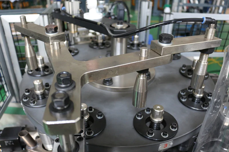
Map the pneumatic test boundary
Use the machine pneumatic diagram to identify the inlet isolation valve, filter, regulator, lubricator where fitted, gauges, manifolds, valves, cylinders, blow points, vacuum generators and drains. Record which accessories or downstream machines share the same header. Do not include unknown factory users in a machine-consumption conclusion.
The air-compressor requirements guide explains supplier confirmation for capacity planning. This article focuses on testing the installed machine boundary after a leak or demand problem is suspected.
Describe the air-related symptom
Record slow cylinder motion, incomplete pickup, weak ejection, unstable vacuum, a regulator drop, compressor cycling, audible leakage or an alarm that appears at a specific cycle event. Note product, speed stage, number of connected machines and whether the condition changes by shift or after maintenance.
Do not diagnose from sound alone. Exhaust silencers, vacuum generators and normal valve switching can resemble leakage. Connect the symptom to a location, machine state and repeatable time.
Use an air-test evidence table
| Observed pattern | Evidence to collect | Diagnostic direction |
|---|---|---|
| Audible flow while isolated and idle | Valve boundary, gauge trend, sound location and component state | Confirm a constant leak inside the defined boundary |
| Pressure stable at idle but drops in cycle | Inlet and downstream pressure, event timing and flow evidence | Review restriction, supply or peak simultaneous demand |
| One actuator moves slowly | Valve output, tubing, fittings, exhaust and mechanical load | Separate local pneumatic loss from machine-wide supply |
| Fault changes with other machines | Header pressure, connected users and synchronized production times | Review shared-system capacity or pressure loss |
| Leak follows hose movement | Hose route, bend, fitting, abrasion and motion position | Find fatigue or contact at the moving connection |
Perform a controlled idle leak check
Follow the site’s lockout and pneumatic isolation procedure. Stored air can move cylinders after electrical power is removed. Where the approved test allows a charged but non-moving state, keep guards in place and personnel outside hazardous areas.
Record starting pressure at defined gauges, isolate the intended boundary and observe the trend for a documented period. Note temperature and stored-volume changes. A pressure-decay comparison is meaningful only when valve positions, cylinder positions and connected volumes are the same.
Locate leakage safely
Use an approved ultrasonic detector, leak-detection solution or other site method suitable for the component and product environment. Inspect fittings, hose ends, valve bodies, cylinder ports, regulator bowls, drains and vacuum circuits. Do not use hands to feel high-pressure leakage or apply an unapproved flammable liquid.
Tag each confirmed location and estimate priority through the factory’s method rather than tightening every fitting immediately. Preserve evidence of a cracked tube, damaged seal or loose support. Vent and verify zero pressure before repair.
Measure demand during the real cycle
Dynamic demand testing requires appropriate gauges or flow measurement installed at approved points by qualified personnel. Record inlet pressure, regulated pressure, flow where available, cycle stage and the actuator or air device operating at each drop. The measurement device must not create an unsafe restriction.
Compare startup, low-stage testing and representative production with the same product and connected-user condition. A single average flow value can hide short peaks. Do not publish a universal pressure or consumption number; use the actual machine specification and supplier-approved operating range.
Separate supply, restriction and machine demand
If pressure falls before the machine isolation point, inspect the shared header, compressor, receiver, dryer and distribution loss with the facility team. If inlet remains stable while regulated pressure drops, inspect filters, regulator capacity, drains and local piping. If both remain stable but one motion fails, investigate that branch and its mechanical load.
The moisture and filtration guide applies when bowls contain water, filters restrict flow or drains fail. Fix leakage and contamination without increasing regulator setting beyond the approved range.
Repair and prove the result
Use compatible tubing, seals, fittings and components confirmed for the delivered machine. Support hoses so motion, heat and sharp edges do not repeat the damage. After depressurization and repair, inspect connections, restore guards and recharge according to the controlled startup.
Repeat both idle and dynamic tests under comparable conditions. Confirm actuator completion, pickup, ejection and product quality. Record leak locations, parts changed, before-after measurements, connected users and test state so future energy or reliability reviews use traceable evidence.
Frequently asked questions
Does a falling regulator gauge always prove a leak?
No. Valve position, stored volume, temperature and connected devices affect the reading. Repeat a defined boundary test before concluding.
Can air leaks be found by touching fittings?
No. Escaping compressed air can injure. Use the site’s approved detection method and depressurize before physical repair.
Should machine pressure be increased when cylinders slow down?
Not automatically. Check supply, restriction, leakage, valve and mechanical load. Higher pressure can exceed component or process limits.
What information helps with an air-demand review?
Provide machine model, pneumatic diagram, test boundary, gauge or flow trends, cycle event, connected users, confirmed leaks and recent component changes.
Send the machine model, pneumatic boundary, regulator and filter evidence, before-after measurements, event sequence and affected motion through our inquiry page. HANNAI can compare them with the supplied pneumatic configuration.