Paper cup machine compressed air moisture and filtration problems can cause sticky valves, inconsistent cylinder motion, contaminated sensors, blocked vacuum generators and unexplained pneumatic faults. The solution is not simply to raise pressure. A professional air-quality review follows the supply from compressor and receiver through drying, drainage, distribution and the machine service unit, then compares evidence while the machine is actually cycling.
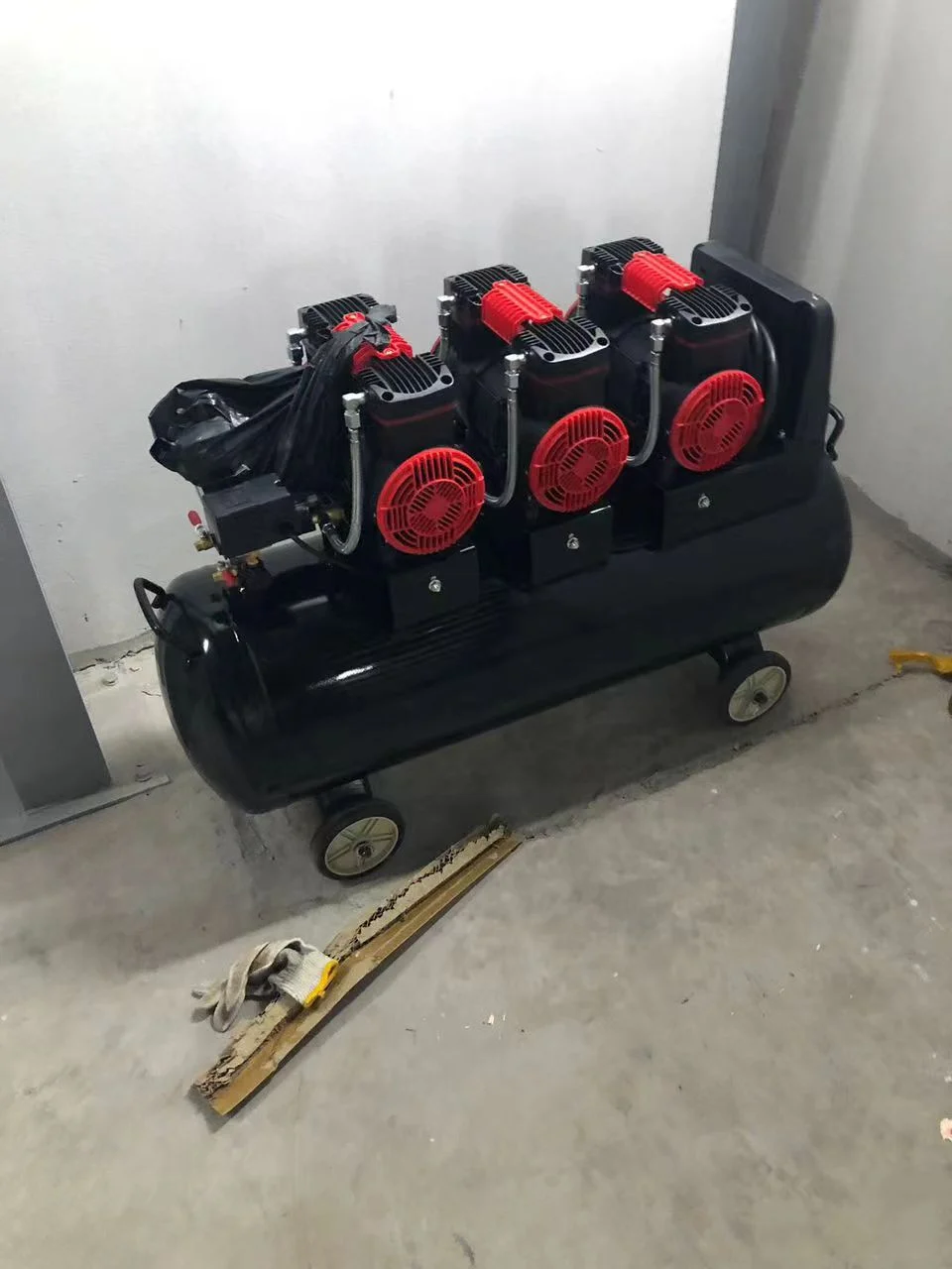
Identify water, oil and particle evidence correctly
Inspect permitted drain points and transparent bowls without opening a pressurized system. Record liquid quantity, colour, odour, particle evidence and how quickly it returns after drainage. Note the ambient condition, compressor operating cycle, receiver drain history, dryer indication and whether the issue affects one machine or the full header.
Condensate downstream does not automatically prove that the machine filter failed. It may originate in inadequate drying, a hot compressor discharge cooling in long pipework, a full receiver, failed automatic drain, poor piping slope, an undersized treatment stage or a local service unit. Oil carryover and process contamination require separate identification and disposal according to site rules.
Use an air-quality evidence table
| Location | Evidence to record | Decision |
|---|---|---|
| Compressor and receiver | Operating state, drain function, maintenance record and visible carryover | Is contamination entering at generation or storage? |
| Dryer and treatment | Installed type, indicators, alarms, drain and service status | Is the treatment stage operating within its approved condition? |
| Main distribution | Pipe route, low points, drops, temperature changes and affected users | Is moisture condensing or collecting in distribution? |
| Machine inlet | Pressure at rest and during cycle, bowl condition and drain result | Does the machine receive stable, treated air under load? |
| Point of use | Valve or cylinder symptom, filter element, hose and local contamination | Is one branch creating restriction or carrying debris? |
| Recovery | Drain volume, fault count and motion result after verified correction | Was the source removed rather than temporarily emptied? |
Confirm the delivered air requirement
Use the nameplate, quotation and manual for the actual machine. HANNAI models have configuration-specific working-air requirements; the correct pressure and consumption must be confirmed for the delivered scope and supporting devices. The air compressor requirements guide explains how to plan capacity without treating nameplate pressure as the complete answer.
Measure pressure at the approved machine inlet while the machine performs its normal cycle. A stable static gauge can hide undersized pipes, closed valves, blocked elements or simultaneous-user demand. Pressure loss and wet air may occur together, but they must be diagnosed as separate conditions.
Trace moisture from upstream to point of use
Begin upstream. Check compressor and receiver drains, the installed dryer and filtration stages, then distribution low points and machine drops. Drain and isolate only by the site’s approved procedure. Compressed air can propel debris and move actuators unexpectedly; never loosen a bowl, hose or fitting under pressure.
Long warm-to-cool pipe runs can create downstream condensation even when the compressor room appears dry. Review piping layout, drainage and temperature conditions with a qualified compressed-air specialist. Do not add a random small filter at the machine and assume it will replace correct upstream drying.
Service the machine air preparation unit correctly
Identify the supplied filter, regulator, drain and lubricator if one is fitted. Depressurize and verify zero energy before opening the assembly. Replace elements by the specified type and direction; a visually similar element may have different filtration or flow performance. Inspect bowls, seals and drains for damage and confirm reassembly before pressurization.
Do not add oil to a non-lubricated system or change lubricator settings without confirming the delivered pneumatic design. Some components are intended for clean, dry, non-lubricated air. Mixing oils can damage seals, contaminate products and make later diagnosis harder.
Connect air quality to the observed machine fault
Map which valves and cylinders share the affected branch. Water or particles can cause delayed spool movement, restricted exhaust, sensor contamination or intermittent sticking, but mechanical binding, voltage, commands and worn seals can create similar symptoms. Follow the pneumatic troubleshooting guide to separate command, supply and actuator response.
After upstream quality is corrected, a contaminated component may still require approved service or replacement. Do not repeatedly cycle a sticking actuator near an exposed mechanism. Preserve the first alarm and involve the machine supplier before dismantling a valve manifold or changing flow controls.
Prove recovery and prevent recurrence
Repressurize gradually using the approved sequence, verify no leakage and observe the system from a safe position. Record inlet pressure under load, drain condition and repeated actuator performance. Run an identified sample and confirm feeding, forming, transfer and finished cup quality before release.
Create an inspection route covering compressor, receiver, dryer, distribution drains and machine service units. The interval should follow equipment instructions and actual environment, not an invented universal schedule. Trend liquid volume, element changes, differential indication where available and pneumatic fault counts.
Frequently asked questions
Will higher air pressure remove moisture-related faults?
No. Higher pressure does not dry or clean the air and may exceed the delivered equipment limit. Verify treatment, distribution and point-of-use condition while maintaining the specified supply.
Is a machine filter enough if the factory has no air dryer?
A point-of-use filter is not automatically a substitute for correctly sized upstream treatment. Required drying and filtration depend on the compressor system, environment, distribution and delivered components.
Can an operator unscrew a filter bowl after closing the inlet valve?
Not until the branch is isolated, depressurized and verified at zero energy under the site procedure. Trapped pressure can remain downstream of a closed valve.
What evidence helps a supplier diagnose recurring wet-air faults?
Provide the air-system diagram, compressor and dryer models, drain photos, inlet pressure under load, affected component, alarm history, maintenance dates, ambient condition and whether other machines share the symptom.
Send the machine model, delivered air requirement, compressor and treatment scope, distribution layout, under-load pressure, drain evidence and pneumatic fault history through our inquiry page. HANNAI can help define the next machine-side check.