A weak 24V DC control supply can create several apparently unrelated faults: sensors may change state late, solenoids may drop out, the HMI may restart and PLC communications may fail. Replacing the supply before measuring the load and distribution can leave the root cause untouched.
This guide treats the power supply, branch protection, wiring and connected loads as one circuit. It does not define a universal voltage tolerance or authorize live cabinet work. Use the exact power-supply manual, machine drawing and qualified electrical personnel.
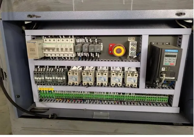
Decision matrix
| Control item | Evidence | Decision |
|---|---|---|
| Power supply identity | Complete model, input range, output rating and status indication | Select the correct manual and replacement |
| Input condition | Measured supply, protection device and terminal condition | Separate upstream loss from DC output failure |
| DC distribution | No-load and loaded voltage at supply and remote devices | Locate voltage drop or overload |
| Connected load | Branch current, startup demand and recent additions | Confirm capacity and fault source |
| Restart proof | Diagnostics, I/O, communications and controlled cycles | Release only after stable operation |
Map the 24V control circuit
Identify the supply input, DC positive and common, protective earth, branch fuses or electronic breakers and every major load. Mark PLC, HMI, sensors, valve coils, relays and communication devices on the drawing. Record recent additions because an extra load can reduce reserve capacity or introduce a short.
Capture the fault time, machine state and indicators before disturbing wiring. A supply that is normal at idle but falls during valve operation needs loaded measurements. A dark output LED alone does not distinguish loss of AC input, internal protection, overload or failed hardware.
Measure input, output and remote voltage
Qualified personnel should use the site isolation and live-test procedure. Compare input voltage at the power-supply terminals with the approved rating, then measure DC output at the supply and at representative remote loads under the same operating condition. Record polarity and instrument reference.
Voltage at the supply can remain normal while a loose terminal, undersized conductor, damaged connector or overloaded branch causes a drop at the device. Do not increase the output adjustment to compensate for distribution loss; first identify the resistance or excessive current.
Separate overload from component failure
Isolate branches only through an approved diagnostic plan and never defeat a safety circuit. Compare branch current and startup behavior with the machine documentation and device data. Inspect for crushed cables, moisture, reversed replacements, shorted coils and recently changed sensors.
Many industrial supplies enter current limiting or protective shutdown during overload. Recovery behavior is model-specific. Do not repeatedly cycle power or replace protection with a larger rating to keep production running. Correct the downstream cause and confirm branch protection remains coordinated.
Approve a replacement as a system component
Match input range, output voltage and rated current, mounting, cooling clearance, terminal style, protection behavior and environmental rating. Confirm how DC common and protective earth are arranged in the original design. A similar wattage label is not enough.
Before removal, label conductors and preserve terminal photographs. Use approved ferrules, conductor sizes and torque procedures. Do not move several conductors into one terminal unless the terminal documentation permits that arrangement. Restore covers and cabinet airflow paths.
Verify the machine after restoration
Confirm stable 24V at the supply and remote loads during startup and representative machine cycles. Review PLC and HMI diagnostics, sensor states, valve response, communication status and emergency-stop reset behavior. Stop if any device restarts or an output drops unexpectedly.
Record the old and new part numbers, measurements, branch currents, wiring work and final test. Send HANNAI the machine model, circuit reference, supply label, voltage trend and fault timing for review. The linked cabinet guide supports the wider terminal and cooling inspection.
Related machine and guide
Review the HN-M100 automatic paper cup machine for machine context, then use the electrical control cabinet inspection guide for the adjacent check. Browse all Buyer Guides when building a wider project checklist.
Frequently asked questions
Can a larger 24V power supply always replace the original?
No. Capacity, protection behavior, mounting, cooling, wiring and circuit coordination must be reviewed.
Why is 24V normal at idle but low during operation?
A startup load, overload, short or high-resistance connection may appear only when devices energize.
Should the output adjustment be increased to correct remote voltage drop?
Not before wiring resistance and load are identified; adjustment can overvoltage other devices.
What should be recorded for support?
Send the supply model, drawing reference, input/output readings, branch loads, fault timing and cabinet photos.
Review your machine configuration with HANNAI
Send the machine model, project reference, component labels, drawings, photos and a description of the required result. We will clarify which details must be confirmed before a quotation or technical recommendation.