A PLC input or output fault is not proven by one inactive indicator. The field device, common circuit, connector, address, program state and module channel all belong to the same signal path. A replacement with a similar terminal count can still have different electrical characteristics or addressing.
This guide is for controlled maintenance on standard process I/O. Safety-rated inputs and outputs require the approved safety architecture and formal validation. Back up the PLC project and isolate hazardous energy before moving conductors or modules.
Decision matrix
| Compatibility item | Record | Why it matters |
|---|---|---|
| Module identity | Family, full code, revision and channel count | Similar housings can use different circuits |
| Signal interface | Digital/analog, voltage/current, PNP/NPN and isolation | Must match the field circuit |
| Addressing | Rack, slot, unit number, channel and PLC tag | Preserves program-to-terminal mapping |
| Wiring | Connector, pinout, commons and branch protection | Prevents channel or polarity errors |
| Validation | Forced state restrictions and point-to-point results | Proves every intended signal path |
Prove the fault location
Record the alarm, LED state, PLC tag and field condition at a known sequence step. Compare the suspect channel with the device indicator and terminal voltage. A sensor can be healthy while the common is open, and an output command can be true while interlocks correctly prevent motion.
Swap tests should be used only when the circuit design and risk assessment allow them. Never move a safety signal or energize an actuator unexpectedly. Inspect removable terminal blocks and connector pins because a loose connector can imitate a module failure.
Back up hardware and address information
Save the current PLC program, hardware configuration, symbols and comments using the approved engineering software. Export an I/O list that maps physical terminals to PLC addresses and machine functions. Record CPU and software versions before opening the rack.
Photograph module order, slot labels, switches, removable connectors and wiring. Some systems allocate addresses automatically from module order; others use unit numbers or configuration entries. The exact platform manual controls the replacement method.
Match the complete electrical interface
Confirm input or output type, channel count, supply, sinking or sourcing behavior, common grouping, isolation, response characteristics and load limits. For analog modules, match signal range, resolution, channel configuration and shielding method.
Do not infer PNP/NPN compatibility from a terminal label alone. Compare the field device, module wiring example and PLC common arrangement. An obsolete-module conversion may require an approved adapter or program change and must be documented as a design revision.
Install without losing the channel map
Isolate power and verify the permitted module-removal state. Protect equipment from electrostatic discharge. Transfer terminal blocks only when the old and new pinouts are confirmed identical; otherwise label and move one conductor at a time against the controlled drawing.
Restore module switches, configuration and address allocation before enabling outputs. Compare the downloaded hardware configuration with the physical rack. Resolve configuration errors rather than suppressing diagnostics or changing addresses until the program appears to run.
Run point-by-point functional tests
Test each affected input with the real field device and observe terminal, module LED, PLC tag and HMI state together. Test outputs in the authorized setup mode with the mechanism controlled, then restore guards and complete slow cycles.
Record every tested channel, expected state and result. Confirm unused points remain inactive and diagnostic flags are clear. Send HANNAI the module codes, rack map, wiring drawing, PLC project inventory and fault evidence when requesting compatibility support.
Technical references
- Omron PLC terminology and memory guidance — general component guidance; the installed machine documentation remains controlling.
Related machine and guide
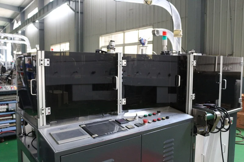
Review the HN-SF160 high-speed paper cup machine for machine context, then use the HMI and PLC communication guide for the adjacent check. Browse all Buyer Guides when building a wider project checklist.
Frequently asked questions
Can a module with the same number of terminals be substituted?
No. Match signal type, commons, channel behavior, address method and electrical limits.
Does a dark input LED prove the module failed?
No. Check the field device, supply, common, connector and wiring first.
Can I/O addresses change after replacement?
They can on some platforms if module order, slot or unit settings differ; preserve the approved map.
What is the minimum commissioning evidence?
A verified backup, matched hardware configuration and point-by-point input/output test record.
Review your machine configuration with HANNAI
Send the machine model, project reference, component labels, drawings, photos and a description of the required result. We will clarify which details must be confirmed before a quotation or technical recommendation.