A contactor is not selected only by its visible size or main-contact current. Coil voltage and frequency, pole arrangement, load category, auxiliary-contact map, mechanical interlock, terminal system and upstream protection all affect whether the replacement performs the same machine function.
This guide treats the contactor as part of the motor, heater or actuator control circuit. Isolate all energy, verify absence of voltage and use the machine schematic plus the exact manufacturer documentation. A contactor with burned contacts may be the result of overload, low coil voltage or excessive switching rather than the original cause.
Decision matrix
| Decision item | Evidence to record | Release question |
|---|---|---|
| Identity | Full code, coil marking, poles and accessories | Is the replacement an approved functional match? |
| Load duty | Controlled load, rated current and switching pattern | Is the contact system suitable for the real duty? |
| Control path | Coil supply, suppression, interlocks and PLC output | Will pickup and dropout remain correct? |
| Auxiliary map | NO/NC states, terminal numbers and feedback use | Are logic and monitoring preserved? |
| Test | Voltage, contact state, load current and repeated cycles | Does the complete circuit work without abnormal heat? |
Prove why the contactor failed
Record the alarm, controlled load and exact point in the cycle. Inspect for welded or eroded contacts, coil discoloration, chatter, loose terminals and heat marks. Measure control voltage during pickup and holding under the qualified live-test procedure; an undervoltage or unstable PLC/relay command can damage a healthy replacement.
Check the motor, heater or other load for excessive current, short circuit, mechanical binding and rapid cycling. Review overload and branch-protection operation. Do not install a larger contactor or bypass an overload simply because the original device failed repeatedly.
Map every main and auxiliary contact
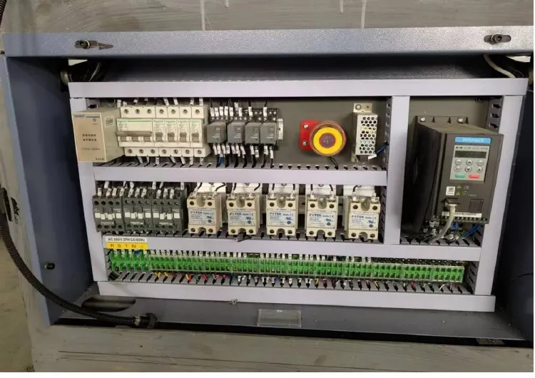
Photograph and label line, load, coil and auxiliary conductors before removal. Trace each auxiliary contact to its function: seal-in logic, PLC feedback, interlock, alarm or external-device monitoring. Record whether the installed block is mechanically linked and whether contacts are normally open or normally closed when the coil is de-energized.
Siemens documentation distinguishes main-contact duty from auxiliary-contact duty and shows that accessories are device-family specific. A replacement can have the same number of terminals but different numbering, timing or mounting. Compare the schematic and datasheets rather than transferring wires by physical position.
Approve the complete replacement assembly
Match manufacturer family or approved equivalent, coil rating, pole count, operational duty, load category, making/breaking capability, auxiliary blocks, suppressor, mechanical interlock and mounting. Confirm terminal conductor range and environmental limits. For reversing or interlocked pairs, replace and align components only under the assembly procedure.
A different coil suppressor can change PLC output loading and release time. A DC coil, AC coil and electronically controlled coil are not interchangeable from a voltage number alone. Document any engineered substitution as a controlled machine change.
Install with controlled wiring and torque
After isolation and zero-energy verification, remove the device without disturbing neighboring wiring. Inspect conductor ends, ferrules, bus links and mounting rail. Re-terminate using the device instructions, approved tools and specified torque; do not double wires into a terminal unless the terminal permits it.
Check coil polarity where applicable, suppression orientation, auxiliary-block engagement and mechanical freedom. Manually operating a device is permitted only if its manufacturer provides that maintenance method and every power and control circuit is disconnected.
Validate pickup, feedback and real load
Restore covers and guards, then energize through the approved startup method. Confirm coil voltage, clean pickup, stable holding, full dropout and correct PLC/HMI feedback. Verify interlocks prevent conflicting contactors and that emergency or normal stops remove the intended output.
Run representative cycles while recording load current, contactor sound and temperature trend. Stop on chatter, delayed release or abnormal heating. Send HANNAI the machine model, schematic reference, both contactor labels, load data and failure photos for compatibility review.
Technical references
- Siemens SIRIUS contactor manual — general component guidance; the installed machine documentation remains controlling.
Related machine and guide
Review the HN-M100 automatic paper cup machine for machine context, then use the electrical control cabinet inspection guide for the adjacent check. Browse all Buyer Guides when building a wider project checklist.
Frequently asked questions
Can a higher-current contactor always replace the original?
No. Coil, duty category, poles, accessories, release behavior, mounting and protection must also match.
Why does a new contactor chatter?
Check coil voltage under load, control output stability, wiring, suppression and mechanical condition.
Can auxiliary wires be moved by terminal position?
No. Transfer them from the verified schematic and contact-state map.
What evidence should accompany a failure report?
Provide device codes, load identity/current, coil voltage, switching pattern, protection status and photos.
Review your machine configuration with HANNAI
Send the machine model, project reference, component labels, drawings, photos and a description of the required result. We will clarify which details must be confirmed before a quotation or technical recommendation.