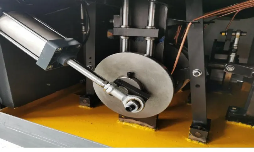
A useful source vacuum reading does not establish what happens at a paper-blank pickup point. The investigation must identify the measured branch, the stage of the handling cycle and the components actually fitted. A check valve is one possible part of that path, not a component that every paper cup machine necessarily uses.
Use this guide when source, branch and pickup observations appear inconsistent. For the initial distinction between missed pickup, loss during transfer and failed release, start with the vacuum pickup overview. Keeping these questions separate avoids repeating the same broad checklist in several articles.
Draw the actual path and mark the observation points
Use the supplied circuit drawing to identify the source, filter, control valve, manifold, hoses, pickup devices and any reservoir or check valve. Mark the measurement points and which branches share components. Confirm flow direction and release arrangement from the component references, not from an assumed layout.
A source indication, branch sensor and pickup observation may represent different locations and moments. Label them before comparing results. Note whether the blank is in contact, the handling mechanism is moving, another branch is operating or release is commanded.
| Observed pattern | Evidence to request | What remains unresolved |
|---|---|---|
| Source indication appears normal, but one pickup fails | Exact measurement locations, branch identity and the handling event | Local contact, restriction, leakage or another branch function |
| Several pickups deteriorate together | Shared circuit path and operating demand at that time | Common source, supply or shared-component behavior |
| Evacuation appears slower | Comparable event timing and documented circuit condition | Restriction, available source performance or leakage |
| Vacuum falls during an intended hold | Defined test boundary, valve states and pickup contact | Where air entered, or whether venting was part of normal operation |
| A blank releases late | Release command, actual material separation and supplied release design | Residual vacuum, mechanical adhesion or transfer timing |
These patterns select the next question. They do not identify a failed part by themselves.
Separate restricted flow from a leaking path
An apparently acceptable static value can coexist with poor response during a short handling event. The Schmalz SCPS-2 instructions explain that restrictive vacuum-side tubing can reduce suction capacity and lengthen evacuation and blow-off times. This supports checking response and circuit condition, not copying that product's hose sizes or settings to another machine.
Ask qualified personnel to define a comparable test from the actual component and machine instructions. Keep source condition, valve state, connected volume, pickup contact and measurement location with the result. Without a defined boundary, a decay observation cannot isolate a check-valve leak from other paths or intended venting.
Do not clamp tubing, cap a branch or substitute a test surface from a generic online checklist. Any isolation test must be appropriate to the circuit and must preserve the machine's protective and release functions. Removing a shared branch may change the conditions for other devices.
Review motion and material as separate variables
If the fault appears during transfer, record the first visible change from a guarded observation position. Hose flex, pickup contact and transfer movement may all vary at that moment; a fault during motion does not prove that a hose is cracked.
Physical inspection requires the specified safe isolated state, including support for mechanisms that could move or drop. Preserve visible abrasion, flattened sections or damaged fittings before authorized replacement. Leave moving mechanisms and internal connections to qualified personnel using the supplied procedure.
Identify the actual fan blank, coating, contact area and stack condition. Do not label all paper blanks porous or blame a new material solely because it was present when the fault occurred. A material comparison needs identified samples and controlled conditions; the fan blank inspection guide covers incoming condition and presentation.
Confirm component function before ordering a replacement
Where a check valve is fitted, obtain its complete code, orientation and intended role. Compatibility includes the documented flow and response requirements, not only port size. Source servicing belongs with the vacuum-source maintenance guide; branch diagnosis should not become an assumed pump-overhaul instruction.
After authorized work, verify the complete pickup, carry and release sequence under the approved trial. Record comparable before/after evidence, any other changes and the relevant finished-cup checks. A better source reading alone is not production-release evidence.
Send HANNAI the circuit reference and event record with the machine identity, marked measurement points, component codes, material lot and safely obtained sequence video. When evaluating the machine range, confirm the actual vacuum arrangement and documentation scope for the proposed project.
Frequently asked questions
Does rapid vacuum decay prove that the check valve leaks?
No. Interpretation requires the test boundary, valve states, connected volume and pickup contact. Other paths or intended venting may explain the observation.
Can an acceptable source reading clear the entire pickup circuit?
No. Identify its location and timing, then compare the relevant branch and handling-event evidence.
Does every coated-paper blank require the same vacuum arrangement?
No. Confirm the actual material and handling requirements through the supplied configuration and representative samples.
Does a fault during motion prove hose damage?
No. Preserve the event and inspect under the approved safe procedure. Contact, transfer timing and other changing conditions also need review.