An intermittent paper cup machine Ethernet link can stop data exchange even when the HMI, PLC and drive remain powered. The useful question is whether the physical link drops, frames are damaged, or a device stays connected but stops providing application data. Those are different diagnostic paths.
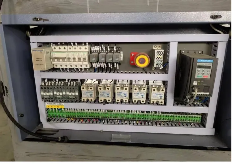
Apply these checks to the actual industrial Ethernet network in the machine. PROFINET, EtherNet/IP and ordinary HMI Ethernet have different configuration and diagnostic tools. The cabinet photograph is general context, not proof that every illustrated machine uses an Ethernet drive network.
Diagnostic decision table
| Evidence | Likely investigation branch | Preserve |
|---|---|---|
| Port link-down event | Connector, cable or device power | Port identity and timestamp |
| Errors rise without link loss | Signal quality or interface issue | Counter change over an interval |
| Link stays up but data times out | Device or application behavior | PLC alarm and device diagnostics |
| Several ports fail together | Shared power or network component | Common event timeline |
Map each endpoint before touching the network
Draw the actual cable route from the affected device to its neighboring port. Include intermediate switches, panel couplers and moving cable sections. Label both ends using the approved drawing, and record the device name and port number. Do not infer topology from cable color.
Save the PLC alarm and relevant device or switch events with a common time reference. A downstream device can appear faulty when an upstream connection resets. If several alarms occur within the same sequence, identify the first event rather than replacing the last component listed on the HMI.
Use counter changes rather than isolated totals
Where supported, record link transitions, interface errors and device uptime at the start and end of a defined observation period. Old accumulated errors can predate the present complaint. Compare the counter increase with production state, cabinet temperature and motion through a suspected cable route.
A link indicator is useful but does not prove successful application communication. Conversely, a timeout alone does not prove damaged copper. Keep the three observations separate: physical link state, interface error trend and controller data availability. Read-only diagnostics should be the first action; avoid resetting switches just to clear the evidence.
Inspect connectors and routing in the safe state
Arrange a controlled shutdown before disconnecting equipment. Follow the electrical isolation procedure for cabinet access. Inspect connector latches, strain relief, contamination and damage at panel couplers. Check whether a cable is stretched when a door opens or when a moving station reaches an end position.
Identify cable construction and connector compatibility with the required protocol and environment. A generic patch lead may not suit continuous motion, oil exposure or industrial shielding requirements. PROFINET installation guidance is relevant to compliant PROFINET cabling, but does not replace the network drawing or authorize changes to other Ethernet systems.
Make one controlled substitution at a time
If permitted by the maintenance plan, replace one suspect segment with an approved, verified cable while retaining the original topology and port assignment. Record exactly what changed. Secure temporary routing away from movement and restore required guarding before testing; a loose diagnostic lead must not become permanent production wiring.
Do not connect an unmanaged office switch, bridge two ports or alter address settings as an experiment. An unintended loop or duplicate address can create a wider outage. If the cable substitution does not change the event pattern, restore the known arrangement and investigate device power, interface condition or software diagnostics with the responsible controls engineer.
Verify the original operating condition
Repeat the production condition associated with the dropout, including relevant station travel or startup events. Compare new link events and counter changes with the baseline. A short idle connection test does not establish reliability during motion or under the original thermal condition.
Document the final cable part, endpoint labels, observation interval and alarm outcome. Preserve unresolved application timeouts separately from resolved physical errors. Send HANNAI the topology sketch and timestamped evidence instead of only a photograph of a red HMI message. This allows support to distinguish wiring repair from a controller, device or network-configuration investigation.
Related equipment and next checks
Review the HN-M100 paper cup equipment and the related guide to HMI and PLC communication diagnosis. The Engineering Notes archive connects these checks with wider machine planning.
Technical reference
- PROFINET cabling and interconnection guidance — general reference; confirm applicability to the installed equipment.
Frequently asked questions
Does a green port light prove correct data exchange?
No. Check application status separately.
Should error counters be reset immediately?
First preserve their values and the timing context.
Can an office cable serve as a permanent replacement?
Only if its specification is approved for the actual industrial use.
Should PLC addresses be changed first?
No. Establish whether the fault is physical or application-related.
Review the evidence with HANNAI
Send your machine model, component identification and the observations described in this guide. Include the drawing or material reference and any before-and-after measurements so the required next check can be identified.