Paper cup heater PID autotune should begin only after the temperature measurement and heater output are trustworthy. Tuning cannot repair a loose thermocouple, a failed heater or an incorrectly configured output. It can also deliberately disturb temperature, making production material unsuitable during the procedure.
Use this readiness guide for a temperature controller that supports an approved autotune function. The machine supplier must define the permissible operating state and thermal limits. No universal PID values, heating temperatures or tuning duration are provided.
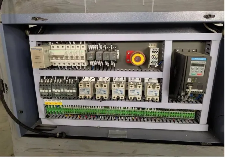
Diagnostic decision table
| Observation | Action before tuning | Evidence |
|---|---|---|
| Temperature reading jumps suddenly | Check sensing and wiring | Raw reading and connection condition |
| Output commanded but no heating | Check output path and heater | Qualified electrical test |
| Temperature rises after output is off | Investigate heat input and switching | Output and temperature trend |
| Stable hardware with repeatable oscillation | Review tuning suitability | Representative process trend |
Define the controlled zone and the real symptom
Identify which heater, sensor and controller belong together. Record the setpoint, measured temperature and output indication during warmup and production. Separate oscillation, slow recovery, persistent offset and overshoot; the same complaint of unstable heat can describe very different faults.
Note recent changes in tooling, material, sensor placement or airflow. A controller tuned for one thermal arrangement may not suit another, but that possibility does not eliminate hardware checks. Preserve the current configuration and alarm thresholds before any change, including output mode and the units used for integral and derivative settings.
Validate sensing and heat delivery first
Have qualified personnel inspect the sensor identity, mounting and electrical configuration through the approved isolation procedure. Check polarity or input type where applicable. Compare independent temperature measurements only at meaningful locations with suitable instruments; a nearby surface reading is not automatically equivalent to the control sensor.
Confirm that the heater output path responds as intended and that switching components are not stuck on or disconnected. Inspect loose thermal contact and unexpected cooling influences. If the temperature continues rising abnormally after output is removed, stop and investigate. Autotune must not be used to compensate for an uncontrolled heat source or a defective protective function.
Establish an authorized tuning condition
Ask the supplier whether tuning should be performed with tooling installed, airflow operating or a representative thermal load. The chosen condition affects the observed process response. Remove or segregate product that could be damaged, and protect adjacent materials according to the machine procedure.
Omron explains that autotuning can introduce deliberate temperature changes to identify control parameters. That behavior requires planned supervision and approved stop criteria. Keep independent over-temperature protection active. Do not run an unattended tuning cycle simply because the controller offers the function, and do not disable an alarm that is interrupting an unsafe temperature excursion.
Run the documented sequence and retain results
Follow the controller-specific start conditions and tuning instructions. Record the initial temperature, setpoint, load condition and completion or failure status. If the procedure aborts, retain the reason before attempting another run. A failed or interrupted cycle does not establish a valid replacement parameter set.
Compare the resulting settings with the saved baseline and document the controller units. Parameters expressed as proportional band are not directly interchangeable with gain values, and time units can differ. Never copy a set from another heater zone without an engineering review of sensor placement, thermal mass and output behavior.
Validate production recovery after tuning
Use a staged restart under the approved process conditions. Compare warmup, steady running and recovery after the relevant production interruption. Review both the temperature trend and actual formed-cup quality; a smoother displayed value does not by itself prove an acceptable sealing process.
Retain before-and-after plots with output indication, material identity and quality results. Confirm that normal disturbances settle within the agreed process limits and that protection remains functional. If the result is worse, use the authorized rollback procedure and investigate the discrepancy. Send HANNAI the full thermal record rather than only the final three PID numbers.
Related equipment and next checks
Review the HN-M100 machine configuration and the related guide to heating and temperature-control diagnosis. The Engineering Notes archive connects these checks with wider machine planning.
Technical reference
- Omron explanation of temperature-controller autotuning — general reference; confirm applicability to the installed equipment.
Frequently asked questions
Can autotune fix a failed heater?
No. Establish functioning hardware first.
Is temperature disturbance during tuning possible?
Yes; plan the procedure and product segregation accordingly.
Can PID values be copied between zones?
Not without confirming compatible process dynamics and parameter units.
Does a smooth display prove good seals?
No. Validate both temperature response and product quality.
Review the evidence with HANNAI
Send your machine model, component identification and the observations described in this guide. Include the drawing or material reference and any before-and-after measurements so the required next check can be identified.