Paper cup ultrasonic frequency drift deserves a trend record when sealing starts normally but later produces frequency-related alarms. The displayed operating frequency reflects the installed ultrasonic system and its loading. A change can guide the investigation, but it is not by itself an instruction to retune the horn or widen generator limits.
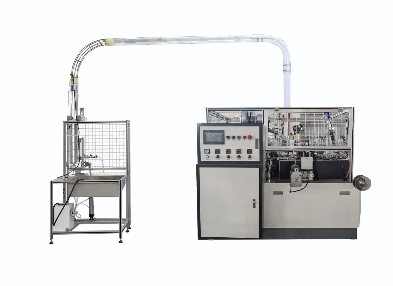
Apply this guide only to the ultrasonic system actually installed. Generator alarm names, tracking functions and permissible checks vary by manufacturer. The reference image provides machine context and does not establish a particular generator brand, frequency or operating limit.
Diagnostic decision table
| Pattern | Investigation branch | Preserve |
|---|---|---|
| Frequency changes as the run warms | Thermal condition and stack behavior | Time-aligned trend |
| Fault appears only during material contact | Load and support conditions | Cycle state and material |
| Alarm begins after stack service | Assembly and compatibility | Parts and service record |
| Displayed frequency is stable but quality falls | Other sealing variables | Product evidence and power/load data |
Identify what the displayed value represents
Record generator, converter, booster and horn identification, together with the applicable manual. Establish whether the available value is a startup scan result, a free-running value, a loaded operating value or another diagnostic quantity. Comparing different quantities as one trend can create a false drift pattern.
Preserve exact alarm codes and timestamps before resetting the system. Note recent stack service, material changes and recipe revisions. Do not transfer frequency limits from another generator simply because the nominal frequency appears similar. The complete approved stack and its control configuration determine what comparisons are meaningful.
Collect a trend in approved operating states
Use existing generator diagnostics to record the relevant value during the authorized startup and production sequence. Associate readings with elapsed run time, material identity, cycle state and the observed seal quality. Where supported, include power or load indicators and an approved non-intrusive temperature observation.
A free-running check must be explicitly permitted by the installed system procedure; do not operate an exposed horn to obtain a convenient reference. Avoid holding parts or measuring tools near energized ultrasonic components. If the system faults, preserve the preceding trend and follow the authorized stop and investigation process rather than repeatedly resetting it.
Separate thermal drift from changes in mechanical loading
Dukane documents that heat and part coupling can shift a stack operating frequency in its systems. Use this as a general reason to compare thermal state with loaded behavior, not as a source of limits for an unidentified paper cup machine. A trend correlated with warming still requires an equipment-specific diagnosis.
If the change occurs only at contact, document the material and support condition, seam location and any recent fixture adjustment. If it develops progressively through the run, compare the approved cooling arrangement and duty condition. Correlation directs the next check; it does not prove whether the converter, horn, interface or process load is responsible.
Review stack service and compatibility safely
Qualified personnel should stop and isolate the system, allow it to reach the specified safe condition and follow the manufacturer’s stack inspection procedure. Confirm part identities and approved assembly records. A horn with the correct apparent shape or nominal frequency is not automatically compatible with the complete system.
Do not grind, drill or machine an ultrasonic component to change resonance. Do not improvise joint torque or apply an unapproved compound to an interface. If the manufacturer requires specialist tuning or inspection, retain the stack identity and arrange that service. Widening tracking limits can conceal a fault and remove useful protection evidence.
Validate recovery with the original production condition
After an authorized correction, repeat the relevant run condition and compare the same diagnostic quantities with the earlier record. Include cold and warmed behavior where the original problem depended on run duration. Verify product seals using the agreed quality method; a frequency trace without alarms is not proof of acceptable cup sealing.
Send HANNAI the component identities, alarm history, time-aligned trend and before-and-after product samples. State which diagnostic values were unavailable rather than estimating them. This evidence helps separate a cooling review, a stack-service issue and a material-loading investigation while preserving the installed generator’s approved protection settings.
Related equipment and next checks
Review the HN-S120 machine configuration and the related guide to ultrasonic converter cooling checks. The Engineering Notes archive connects these checks with wider machine planning.
Technical reference
- Dukane application note AN529 on ultrasonic overload diagnostics — general reference; confirm applicability to the installed equipment.
Frequently asked questions
Does a frequency change prove that the horn is defective?
No. Consider temperature, loading, assembly and the exact diagnostic value.
Can limits from a similar generator be reused?
Use only the settings and procedures approved for the installed system.
Should the horn be modified to restore its frequency?
No. Resonant components require approved specialist inspection and service.
Does an alarm-free run prove seal quality?
No. Verify the finished cups with the agreed inspection method.
Review the evidence with HANNAI
Send your machine model, component identification and the observations described in this guide. Include the drawing or material reference and any before-and-after measurements so the required next check can be identified.