Paper cup machine ultrasonic cooling deserves attention when a sealing station works after startup but develops alarms or weak seams as production continues. A warm-run problem may involve the converter, generator, tooling load or the cooling supply. Increasing amplitude before separating these causes can make the investigation less reliable.
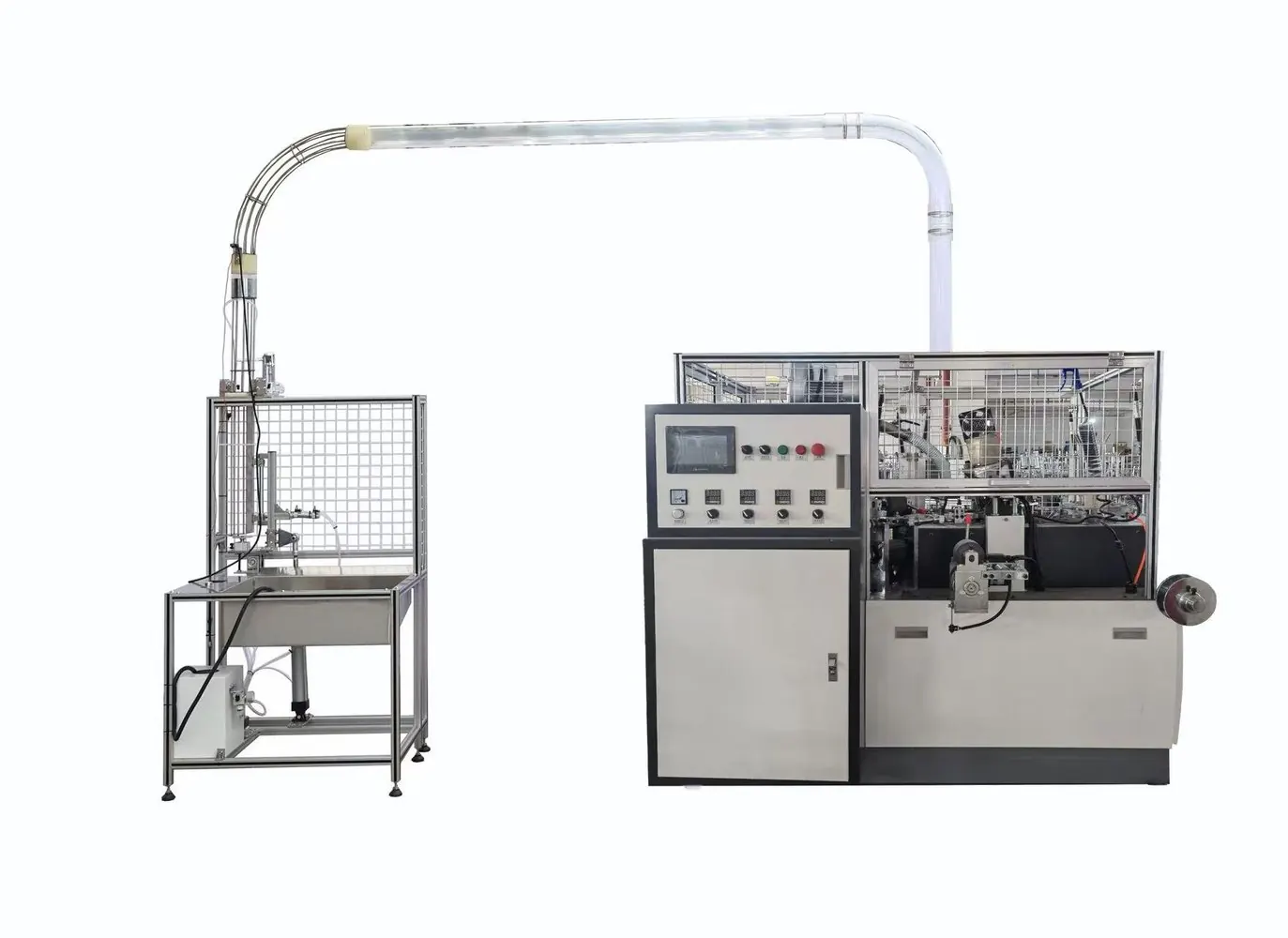
This guide is for a station confirmed to use ultrasonic sealing. Identify the converter, booster, horn and generator as a matched assembly. The photograph shows machine context, not proof of a particular cooling circuit or converter brand on every configuration.
Diagnostic decision table
| Event | Evidence to compare | Avoid assuming |
|---|---|---|
| Alarm appears only after sustained running | Duty history and temperature trend | That the horn alone is defective |
| Cooling line is present but flow is uncertain | Approved point-of-use flow check | That supply pressure proves flow |
| Seal changes after a tool replacement | Part identities and assembly record | That extra cooling corrects incompatibility |
| Generator enclosure is obstructed | Inlet and outlet condition | That converter cooling cools the generator |
Capture the warm-run boundary
Record the time from restart to the first abnormal seal or alarm. Keep cup material, station speed, weld settings and ambient conditions with the record. Label early accepted samples and later suspect samples so the physical seam can be compared with the machine timeline.
Use the generator display and specified temperature monitoring method. Do not touch an operating ultrasonic stack to judge heat or attach an unapproved sensor that alters the vibrating assembly. Record where each temperature is measured; converter body, horn and generator enclosure readings are not interchangeable.
Identify the cooling design before altering it
Obtain the converter and generator manuals and the machine pneumatic drawing. Determine whether the converter uses directed air, another cooling method or a duty limitation without an added cooling connection. Industrial ultrasonic suppliers offer different arrangements, so there is no universal airflow or temperature setting for all stacks.
Trace the installed cooling path without disconnecting it during production. Record the filter, regulator, valve and delivery point where fitted. Ask the supplier which condition must be measured and at which point. A normal gauge reading upstream of a blocked restriction does not demonstrate adequate cooling at the converter.
Inspect supply quality and restrictions
After the approved shutdown and energy isolation, inspect cooling hoses, fittings, nozzles and accessible passages for damage or contamination. Check whether recent maintenance rerouted or pinched a line. Use only the cleaning procedure compatible with the component; do not push debris into a converter.
Where compressed air is required, verify the specified air quality and actual delivered flow using approved test points. Avoid applying wet or oily workshop air to components that require cleaner service. Record simultaneous air demand from other stations when the problem appears, but do not exceed approved pressure to compensate for a restriction.
Separate heat removal from excessive process loading
Compare the fitted stack component identities with the approved assembly. Review tool replacement, joint preparation and mounting records with authorized service personnel. An incompatible horn, damaged joint or changed process load requires correction in its own right; cooling should not mask it.
Inspect the generator ventilation path separately and preserve all thermal protection functions. Review production duty and weld settings against the validated recipe. Do not drill cooling holes, add a clamp, alter stack geometry or repeatedly reset an overtemperature alarm. Those changes can affect mechanical behavior and service safety.
Verify sealing after thermal stabilization
Once the responsible technician approves restoration, repeat the representative production duty with guards closed. Track the original temperature indication, alarms and seam results from startup into the period that previously caused the fault. Use the agreed seam integrity test, not appearance alone.
Keep the original and corrected records together, including the delivered cooling condition and exact component identities. Send HANNAI the generator alarm, assembly labels and sample timeline. A successful review should establish both acceptable cooling behavior and stable seam quality without relying on unapproved settings or a shorter demonstration run.
Related equipment and next checks
Review the HN-S120 machine configuration and the related guide to ultrasonic sealing system troubleshooting. The Engineering Notes archive connects these checks with wider machine planning.
Technical reference
- Herrmann example of separately specified ultrasonic cooling functions — general reference; confirm applicability to the installed equipment.
Frequently asked questions
Is one cooling pressure suitable for every converter?
No. Use the requirement for the installed assembly.
Does converter cooling also cool the generator?
Not necessarily; inspect the generator ventilation separately.
Should amplitude be increased when warm seams weaken?
First separate thermal, tooling and material causes.
What proves that the correction works?
A representative warm run with acceptable alarms, temperatures and tested seams.
Review the evidence with HANNAI
Send your machine model, component identification and the observations described in this guide. Include the drawing or material reference and any before-and-after measurements so the required next check can be identified.