Paper cup bottom recess depth is the vertical relationship between a defined support datum and the selected bottom feature. Mapping it around the cup can help explain rocking, stacking or bottom-form observations. A single center reading does not describe a tilted or locally distorted base.
This article is a dimensional investigation guide, not a source of product tolerances. Use the approved cup drawing to define the datum and feature. Keep recess geometry separate from bottom-seal integrity, which requires its own inspection and functional tests.
Diagnostic decision table
| Observed result | Controlled follow-up | Do not assume |
|---|---|---|
| Depth changes around one cup | Map seam-relative orientation | One center reading represents the base |
| All cups differ at one fixture point | Check datum surface and probe alignment | Production is the only source of bias |
| Packed cups show a new low spot | Compare discharge and packed samples | Forming created downstream damage |
| Depth improves after adjustment | Repeat seal and stability checks | Geometry alone releases the cup |
Define the datum and bottom feature
Use the product drawing to identify the support ring or other reference plane and the exact bottom surface to be measured. State whether the recess is evaluated at the center, at a specified radius or through a profile. The inner bottom panel, knurled joint and external support ring are different features.
Mark orientation relative to the sidewall seam and label every cup by production source. Photograph the original base before measurement. Remove loose debris only through an approved method; pressing the panel or scraping the joint can change the geometry and destroy useful evidence.
Develop a stable non-damaging setup
Support the cup at the intended datum without crushing the base ring. Check fixture flatness, cleanliness and probe alignment with suitable references. Use a satisfactory control cup to reveal a localized fixture issue. If the measurement changes when the cup moves to another fixture position, investigate the setup.
Specify the seating force, probe contact and zero procedure. Flexible coated paper can deflect under contact, so a method chosen for rigid metal components may need adaptation. Have the metrology specialist evaluate the force and uncertainty rather than assuming a low-force probe is automatically non-distorting.
Map several locations and repeated setups
Collect readings at defined angular positions and radii, preserving their orientation. Report the individual map and derived quantities required by the drawing. An average recess depth can appear stable while one sector approaches the support plane or another is unusually deep.
Repeat selected cups after complete removal and replacement. If different operators will use the method, include them in method verification. NIST calibration policy notes that measurement results should be accompanied by an uncertainty statement; for factory decisions, at minimum document the major setup, instrument and operator contributions relevant to the requirement.
Compare process and handling stages
Collect cups near discharge, after stacking and after packing using a traceable sampling plan. Compare the orientation and shape of confirmed changes. Bottom deformation concentrated after packing may be associated with compression or handling even when the forming station is stable.
Map results by forming position, material lot and time where available. Inspect bottom roll, knurl pattern, support ring and leakage separately. Do not change bottom heating, pressure or tool depth because a recess map looks asymmetric until the responsible feature and approved adjustment have been reviewed with the supplier.
Confirm geometry and functional quality together
After an authorized correction, repeat the original map on representative cups without changing the measurement rules. Include startup, steady run and relevant handling. Preserve raw data and rejected observations with their reasons instead of presenting only the final average.
Verify base rocking, stacking and liquid integrity through their approved methods. Send HANNAI the cup drawing, datum sketch, orientation maps and process identity. This combination can show whether the issue follows a station, handling step or material group without treating recess depth as a substitute for overall cup acceptance.
Related equipment and next checks
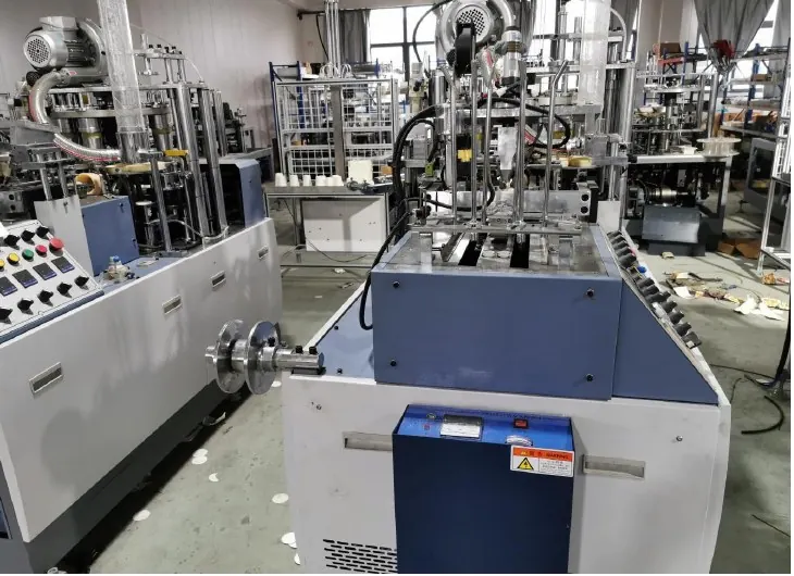
Review the HN-M100 paper cup forming equipment and the related guide to bottom knurling and base-seal inspection. The Engineering Notes archive connects these checks with wider machine planning.
Technical reference
- NIST: dimensional calibration and measurement assurance — general reference; confirm applicability to the installed equipment.
Frequently asked questions
Is the deepest point always at the cup center?
No. Define the measurement locations and map the relevant profile.
Can the support ring be pressed flat during measurement?
Only if the approved method accounts for the deformation it introduces.
Does correct recess depth prove the bottom will not leak?
No. Liquid integrity requires a separate suitable test.
Should one asymmetric map trigger a machine change?
Confirm repeatability and production pattern before authorizing an adjustment.
Review the evidence with HANNAI
Send your machine model, component identification and the observations described in this guide. Include the drawing or material reference and any before-and-after measurements so the required next check can be identified.