A paper cup machine forming mandrel provides the reference surface around which the sidewall, bottom and upper features are formed. A scratched, contaminated, loose or off-center mandrel can produce repeatable scuffing, dimensional variation, poor transfer, seam instability or uneven rim behavior. A useful inspection separates the mandrel itself from support bearings, mounting faces, tooling contact and incoming blank variation before anyone changes machine timing.
Confirm the mandrel and cup feature under review
Identify the machine model, mandrel position, cup size, tooling set and product feature that first showed a change. Record whether the concern follows one mandrel, every station, one material lot or one operating condition. A station-numbered sample sequence is more useful than a mixed bag of rejected cups.
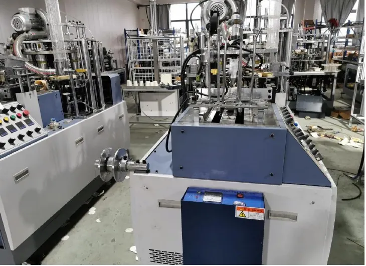
Review the delivered tooling drawing and changeover record before measurement. The relevant diameter, taper, shoulder, locating face, fastener arrangement and surface requirement are configuration-specific. The HN-M100 paper cup machine page shows the forming context, but actual mandrel acceptance values must come from the supplied project documents.
Map the defect around the cup circumference
Mark each cup with machine, station, direction and time. Note whether a scratch, wrinkle, seam displacement or dimensional change appears at the same angular position. Compare the mark with seam location, bottom contact, rim-tool direction and transfer orientation. A defect fixed to the mandrel angle suggests a different cause from one fixed to the paper blank.
Preserve first-off good samples, recent bad samples and the material identification. Do not clean or polish the suspected mandrel until the original contact pattern has been photographed under suitable light.
Use a mandrel-condition evidence table
| Observed condition | Evidence to collect | Diagnostic direction |
|---|---|---|
| Scuff repeats at one angle | Station-marked cups, mandrel surface photo and transfer orientation | Look for a local burr, deposit or tooling contact |
| Cup diameter varies by station | Referenced measurements, mandrel identity and mounting condition | Check mandrel geometry and support movement |
| Cup releases unevenly | Release direction, surface condition, air path and transfer timing | Separate friction from sequence problems |
| Runout changes after warm-up | Cold and stable-state readings, support temperature and fastener marks | Review support, fit and thermal influence |
| New mandrel also marks cups | Locating face, adjacent tooling, material and installation record | Find the system source before replacing more parts |
Isolate motion and stored energy
Apply the approved lockout procedure and verify electrical, pneumatic, vacuum, gravity and spring energy are controlled. Use the documented machine position and blocking method before placing hands or measuring equipment near the forming turret. A stopped drive does not prove that an indexed station cannot move.
Photograph timing marks, shims, fastener witness marks, mandrel orientation and neighboring tooling before loosening anything. Do not rotate an individual station or alter a locating feature unless the service procedure permits it.
Inspect the surface without changing it
Under clean directional light, inspect the full working length for transferred coating, paper dust, adhesive, corrosion, impact dents, raised edges, scoring, discoloration and polish bands. Use an approved cleaning method compatible with the mandrel material and food-packaging environment. Aggressive abrasive work can change geometry and hide evidence.
Where a mark is found, compare its height and angle with the defect map. Check whether adjacent forming, sealing or release parts could touch the same area. A surface deposit may be the result of incorrect contact elsewhere rather than the original cause.
Measure runout and concentricity from a valid reference
Confirm which locating diameter or face establishes the measurement reference. Qualified personnel should use the specified fixture and instrument, verify the surface is clean, and record readings at defined axial positions while following the approved rotation method. Hand-spinning a loaded station may not produce a valid result.
Separate mandrel body runout from mounting-face error, spindle movement and instrument setup. Record instrument resolution, reference location, machine state and repeated readings. Compare only with the supplier drawing or an approved known-good station; do not invent a universal tolerance.
Check the mounting and support path
Inspect the mandrel retaining fastener, taper or locating fit, flange face, key or anti-rotation feature, spindle, bearings and station support. Look for contamination trapped under a face, fretting, displaced witness marks, damaged threads, loose retention or abnormal play. A correct mandrel mounted on a damaged reference can still run off-center.
If movement appears under load but not during an unloaded check, examine the support and forming-force path. Replacement decisions should include the mating components, not only the visible mandrel.
Separate tooling geometry from paper variation
Compare paper thickness, coating, blank dimensions, seam overlap and storage condition with approved material. Inspect the surrounding forming, bottom and rim tools for contact marks or buildup. One material lot may reveal a marginal setup, while a persistent station-specific defect points more strongly toward tooling or support.
Use the paper cup dimensional consistency guide to define repeatable sample locations. Do not adjust the mandrel to compensate for an unverified blank or measurement problem.
Prove the complete station in controlled stages
After approved cleaning or service, confirm fastener condition, tooling identity, clearances, air paths and guards. Use the documented manual or slow-cycle sequence to verify that the mandrel clears every adjacent component throughout indexing, forming and release.
Run labeled cups in small stages before normal production. Measure the affected feature, inspect the full circumference and compare release, seam and rim behavior across stations. Record the final readings, samples, work performed and authorization for return to service.
Frequently asked questions
Can a smooth-looking mandrel be assumed concentric?
No. Surface appearance does not prove that the mandrel, mounting face, spindle and support rotate around the intended reference.
Should a scratched mandrel be polished immediately?
No. Preserve the contact evidence and confirm the repair method. Uncontrolled polishing can change diameter, taper or surface finish.
Can one tolerance be used for every paper cup machine?
No. Acceptance depends on the supplied machine, mandrel design, cup dimensions, material and measurement method.
What evidence should be sent to the supplier?
Send machine and tooling identity, station-marked cups, defect maps, surface photos, referenced runout readings, support observations and recent service history.
Send the machine model, cup drawing, tooling identity, station-marked samples, isolated surface photos, referenced measurements and service history through our inquiry page. HANNAI can review the evidence against the supplied machine configuration.