A safety relay is part of a complete safety function, not an ordinary control relay. Its input channels, reset mode, contact monitoring, output arrangement and fault detection must remain consistent with the machine risk assessment and validated circuit.
Replacing it solely by terminal count can remove diagnostic coverage or change restart behavior. Work must be completed by qualified safety-control personnel using the exact schematic and device documentation. Production demand never justifies bypassing a guard or emergency stop.
Decision matrix
| Safety element | Evidence | Validation question |
|---|---|---|
| Relay identity | Complete code, supply, outputs, delay and approvals | Is the proposed unit the approved equivalent? |
| Input architecture | Single/dual channel, test pulses and cross-short detection | Is fault detection preserved? |
| Reset and feedback | Manual/automatic reset and external-device monitoring | Can restart occur only as designed? |
| Output devices | Contactors, drives and monitored auxiliary contacts | Does removal of energy remain effective? |
| Function test | Every guard, E-stop, reset and fault scenario | Does the whole safety function pass? |
Freeze the safety design before work
Obtain the current electrical schematic, risk assessment, safety-function description and last validation record. Record the exact relay and expansion units, terminal links, delays, reset device, contactors and drive safety inputs.
If documents disagree with the installed circuit, stop and resolve the configuration. Do not treat an undocumented jumper as normal. Photograph conductors and terminal identifiers without moving them, and record the reason for replacement and diagnostic behavior.
Approve the replacement architecture
Match supply voltage, input channels, output contacts, response or off-delay functions, reset logic, external-device monitoring and environmental requirements. Omron notes that safety performance is determined by the complete control system, not by the relay certificate alone.
A newer relay may need different terminals or test behavior. That is a safety design change, not a maintenance shortcut. Use a competent person to confirm achieved performance and required standards for the actual machine and destination.
Control wiring and reset behavior
Isolate energy and verify zero-energy conditions. Transfer conductors against the schematic, using correct terminal hardware and torque. Confirm contactor feedback and reset wiring are not confused with the safety inputs.
Manual and automatic reset modes are not interchangeable. Reset must not initiate hazardous motion, and its location must support the intended visibility and access control. Never bridge a feedback loop to make a relay reset.
Validate every initiating device
With the machine in a controlled state, test each emergency stop, guard switch and other safety input individually. Confirm safety outputs remove the intended energy, the machine cannot restart while the device is open, and reset is required or automatic only as designed.
Test channel discrepancy, welded-contactor monitoring and fault diagnostics using the approved validation method. Do not create dangerous shorts casually. Measure stopping performance when the risk assessment requires it and compare with the approved limit.
Close the safety change formally
Record relay and expansion-unit codes, wiring verification, software or parameter status, test instruments, every validation step, results and responsible approver. Update drawings and the spare-parts list when an approved conversion was made.
Send HANNAI the machine reference, safety schematic, relay labels, diagnostic evidence and required safety-function description. The linked guard verification guide provides the mechanical and operational checks around the relay circuit.
Technical references
- Omron G9SA safety relay documentation — general component guidance; the installed machine documentation remains controlling.
Related machine and guide
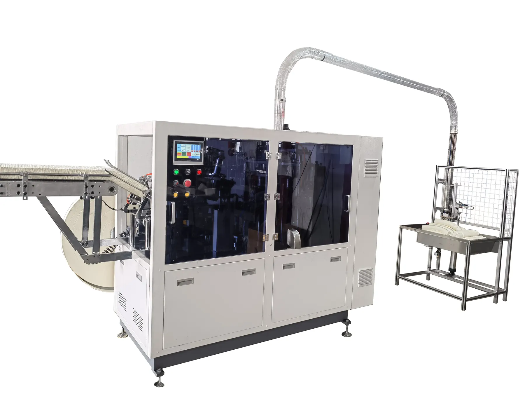
Review the HN-SF160 high-speed paper cup machine for machine context, then use the emergency stop and guard verification guide for the adjacent check. Browse all Buyer Guides when building a wider project checklist.
Frequently asked questions
Can an ordinary relay replace a safety relay?
No. Safety relays provide defined architecture and monitoring that an ordinary relay does not replace.
Can reset wiring be changed to automatic for convenience?
Not without a complete safety review and validation of the machine application.
Does a certified relay make the whole machine safety compliant?
No. Performance depends on the complete input, logic, output and mechanical safety function.
What must be tested after replacement?
Every initiating device, stop output, reset condition, feedback path and applicable fault response.
Review your machine configuration with HANNAI
Send the machine model, project reference, component labels, drawings, photos and a description of the required result. We will clarify which details must be confirmed before a quotation or technical recommendation.