Paper cup machine transfer grippers and guides have to present a partly formed cup or component to the next station without changing its geometry. Wear can appear as a small timing-dependent scuff, tilt or intermittent miss long before a component breaks. A professional inspection therefore traces the product through each handoff, identifies the first changed condition and measures the mechanical evidence under safe isolation.
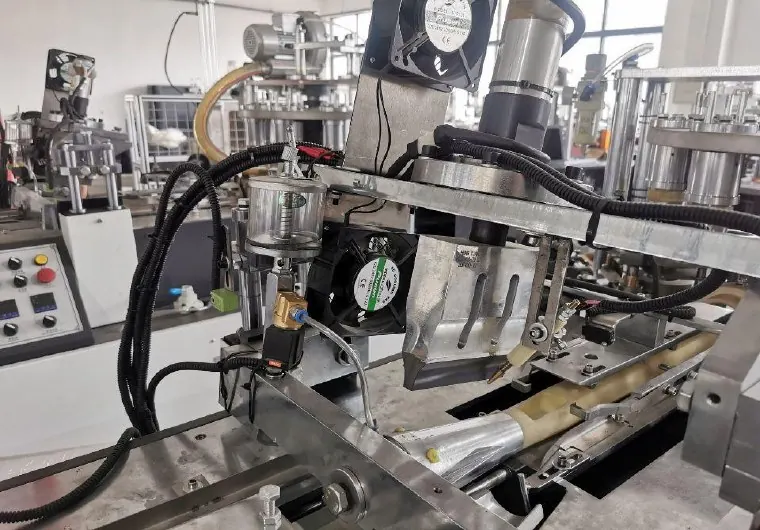
Map every product handoff
Use the delivered process drawing or manual to name the relevant pickup, gripper, pocket, mandrel, guide, stop and release point. The exact arrangement varies by model and cup process. Identify what each element receives, how it locates the part, when it releases it and which surface should never mark the product.
Mark station numbers on an inspection sheet, not on the machine unless the supplier approves the method. The indexed turntable alignment guide is useful when the entire station relationship is displaced. This guide focuses on local contact, support and transfer wear within an otherwise understood sequence.
Capture the first abnormal product condition
Collect consecutive cups before and after the suspected handoff where the safe sampling method allows. Label them by time and station. Look for a repeated scrape, dent, oval rim, crushed edge, tilted bottom, open seam, double impression or release mark. A final cup may carry several secondary marks after the first transfer error.
Record whether the symptom changes after startup, at a specific speed stage, with one cup size, after a jam or as components warm. Compare accepted material and tooling rather than combining several variables. A defect that follows one blank or bottom-paper lot may not be mechanical wear.
Use a transfer-wear evidence table
| Observed pattern | Evidence to inspect | Decision direction |
|---|---|---|
| Repeat mark at one cup height | Mark orientation, guide face, burr, residue and local clearance | Match the product mark to a physical contact point |
| Intermittent tilted transfer | Pickup depth, gripper symmetry, looseness and incoming geometry | Separate unstable grip from an already deformed cup |
| Cup retained after release | Surface contamination, vacuum state where fitted and release motion | Check adhesion or incomplete release before changing timing |
| Fault increases with speed | Motion video, support condition, backlash and sequence margin | Find the handoff that loses controlled contact |
| Fault began after changeover | Installed part identity, seating, fasteners and reference marks | Confirm the matched change-part set and setup |
Inspect contact surfaces under isolation
Apply lockout and verify isolation before entering guarded areas or touching transfer mechanisms. Clean only by the approved method so that residue is not mistaken for wear. Use good lighting and a safe viewing angle to inspect gripping faces, guide edges, inserts, springs, pins, bushings, fasteners and mounts that are accessible under the maintenance procedure.
Look for polished tracks that differ from the reference condition, chipped edges, grooves, mushroomed stops, bent guides, cracks, contamination, loose joints and unequal left-to-right contact. Photograph the product mark beside the suspected machine surface. Do not file, bend or shim a part before its condition and installed reference are recorded.
Measure against the supplier reference
Wear limits, gripping force, clearance, alignment and tightening methods depend on component design. Obtain the drawing, manual or HANNAI instruction for the machine. Use calibrated tools appropriate to the reference and record measurement points so that the next inspection can be compared.
A gap that appears unequal may be caused by bearing play, shaft movement, a loose mount or an incorrectly seated change part. Check the complete support chain before ordering the visible guide. If the mechanism is spring- or air-loaded, discharge stored energy according to the maintenance procedure before inspection.
Separate transfer wear from timing and utilities
A healthy gripper can miss a cup when the upstream station presents it late, an air actuator does not complete, vacuum falls under demand or the index position changes. Compare the mechanical mark with alarm history, motion completion signals and the first abnormal cycle. Avoid changing timing to compensate for a component that cannot hold its designed reference.
Use the pneumatic troubleshooting guide when actuator motion or gripping force depends on the air system. Confirm pressure and flow by the approved method at the relevant operating condition; a static regulator reading alone does not prove the motion completed correctly.
Replace as a controlled mechanical task
Confirm the part number, machine model, product range and whether components must be replaced as a matched pair or set. Preserve shims, spacers and orientation records. Qualified maintenance personnel should secure stored energy, support moving assemblies, install to the supplier reference and apply the specified fastening method.
After installation, manually verify movement only where the documented procedure permits it. Check that tools and loose items are removed, guards are restored and the area is clear. Do not use a hand near the product path to judge whether a gripper closes evenly.
Prove the repair with product evidence
Follow the approved restart sequence and advance through controlled stages. Compare external motion and sensor status, then inspect consecutive first-off cups at the same locations used before repair. Verify dimensions, seam, rim, bottom, surface and stacking as relevant; a removed scuff does not prove every transfer relationship is correct.
Record the replaced or adjusted part, measured condition, setup reference, trial material, operating stage and sample result. Keep the removed component long enough for cause review. Trending wear by product cycles or documented operating history is more useful than replacing every guide on an arbitrary calendar date.
Frequently asked questions
Does every scuff on a cup mean a transfer guide is worn?
No. Residue, a burr, incorrect setup, material behavior or upstream deformation can create a similar mark. Match the first product mark to a confirmed contact point.
Can a guide be bent back into position during production?
No. Uncontrolled bending can weaken the part and hide the reference. Isolate the machine, document condition and follow the supplier’s repair or replacement instruction.
Should grippers always be replaced one at a time?
Not necessarily. Some designs use matched components. Confirm the parts list, wear relationship and supplier recommendation for the delivered machine.
What evidence is most useful for remote diagnosis?
Send labeled consecutive samples, photographs of contact marks and isolated components, the first-fault sequence, safe external video, part identity, measurements and recent changeover or jam history.
Send the machine model, cup drawing, affected station, labeled samples, isolated mechanism photos, measurements and a safe cycle video through our inquiry page. HANNAI can review the transfer path against the supplied configuration.