Roll die cutting machine cutting pressure and die alignment troubleshooting should distinguish the cutting rule, die board, counter or support surface, impression distribution, web presentation and material response. Incomplete cuts on one side and crushed edges on the other are evidence of an uneven system, not a reason to increase overall loading without a controlled inspection.
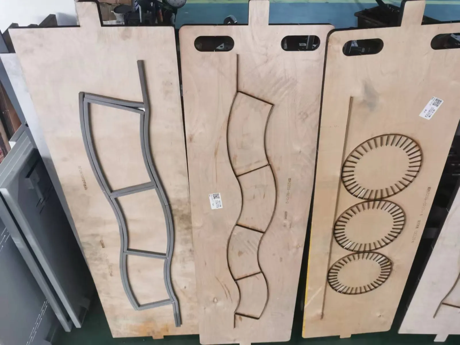
Classify the cut defect precisely
Identify whether the sheet or web shows an uncut bridge, intermittent incomplete cut, excessive penetration, crushed edge, torn coating, burr, poor crease, dimensional shift or repeated damage at one location. Mark machine direction and operator side on consecutive samples so the defect can be mapped back to the die and machine.
Do not combine cut quality and print register into one vague complaint. A blank can be fully cut but positioned incorrectly relative to print, or correctly registered but incompletely separated.
Use a pressure and alignment evidence table
| Check point | Evidence to collect | Diagnostic question |
|---|---|---|
| Material | Board identity, thickness or caliper method, coating and lot | Has material response changed? |
| Die | Die ID, drawing revision, cutting-rule and crease condition | Is the correct and serviceable die installed? |
| Defect map | Orientation-marked consecutive samples | Does the fault stay at a fixed machine or die location? |
| Mounting | Reference marks, fasteners, seating and visible contamination | Is the die aligned and supported as intended? |
| Impression | Approved setting reference and across-width cut evidence | Is loading even rather than merely high? |
| Web path | Tension, lateral position and register evidence | Is moving material changing the apparent cut location? |
| Release | Cut, crease, dimensions and downstream forming results | Has the blank function been proven? |
Confirm the material and die match the job
Verify the board, coating, roll orientation, blank drawing and die revision before changing machine settings. A die made for another blank revision may appear close while producing wrong clearances or dimensions. Confirm whether the installed die and any matched support or counter component belong together.
The paper cup blank and die-cutting guide explains the relationship between the blank drawing and downstream cup forming. Preserve traceability to the material roll and die set.
Map defects across the die and machine
Collect consecutive cuts and mark operator side, drive side, machine direction and repeat number. If the uncut area stays at the same die location, inspect that rule and its support. If it stays on one side across different die features, investigate alignment or impression distribution. If it moves with the web, investigate tension, lateral guiding or material variation.
This map prevents a local defect from being treated with a global pressure increase. It also helps distinguish a damaged rule from a machine-wide geometry issue.
Inspect die seating and reference condition safely
Stop, isolate and control stored mechanical, pneumatic and electrical energy before entering the cutting area. Verify the die identity, mounting surface cleanliness, fastener condition, reference stops, alignment marks and visible seating. Look for trapped scraps, adhesive buildup, damaged backing or a loose component.
Never reach into the cutting zone during jog, and never rely on an HMI stop alone. Removal, repair and packing of a die require trained personnel and the die supplier’s approved method.
Evaluate impression distribution before increasing load
Use the delivered test and adjustment method to compare cut evidence across the working width and repeat. The goal is adequate, even cutting without excessive penetration or damage. A high overall setting cannot correct a tilted, contaminated or locally damaged interface.
Do not insert unapproved shims or pack local areas by improvisation. Such changes can concentrate load, damage the die or machine and distort blank dimensions. Record every authorized correction and preserve the original reference.
Check cutting rule, crease and support condition
Under safe isolation, inspect rule edges, joints, ejection material, crease components and the opposing or supporting surface as applicable to the delivered die system. Look for local wear, breaks, contamination, compression set and evidence of uneven contact. A clean cut edge and a functional crease require different geometry, so both must be inspected.
Tooling repair belongs to qualified die personnel. Replacing or bending a rule without controlling dimensions and joint condition can create new downstream problems.
Separate web register from die geometry
If the cut outline shifts relative to printing while its dimensions remain stable, investigate the web and register path. If dimensions or cut completeness change at a fixed die position, focus on tooling and impression. Use the web tension and register control guide for unwind, tension, sensor and printed-mark evidence.
The artwork registration checklist helps confirm that the drawing, print file and cutting reference use the same approved geometry.
Prove cut quality in downstream forming
After correction, restore guards and run the staged procedure approved for the machine. Collect consecutive blanks across the working width and inspect cut completion, edge quality, crease, dimensions and print relationship. Retain samples linked to material and die identity.
A blank is not fully accepted until it separates, feeds and forms correctly downstream. For machines such as the 850 roll die cutting machine or 950 roll die cutting machine, the exact setup remains dependent on blank drawing, roll width and material.
Frequently asked questions
Should overall pressure be increased when only one corner is not cut?
Not before mapping the defect. A local rule, seating or support problem is more likely to need a local verified repair than a machine-wide load increase.
Why are cuts complete but blank edges crushed?
Excessive or uneven impression, worn support, damaged tooling or unsuitable material response may be involved. Compare across-width evidence and the approved die setup.
Can operators add shims under a low area?
Only if the machine and die supplier provide an approved method performed by trained personnel. Improvised packing can concentrate load and damage equipment.
What should be sent to the die or machine supplier?
Provide the blank and die revisions, material record, orientation-marked samples, defect map, safe photos of the isolated die, approved setting reference and change history.
Send the machine model, die and drawing identity, material construction, orientation-marked cut samples, defect map, approved setup record and isolated-condition photos through our inquiry page. HANNAI can help review the evidence and configuration boundary.