Paper cup mold selection starts with finished-cup geometry rather than a nominal ounce size. Two cups sold under the same volume description can have different diameters, heights, taper and rim profiles. Those differences affect tooling, sidewall blanks, bottom material and downstream handling.
Give the supplier an identified sample or approved drawing before requesting a tooling proposal. Keep the revision consistent across the cup, lid and material records so a later change does not leave the production setup based on an earlier design.
Define the cup with measurable information
Provide top diameter, bottom diameter and height with units and the agreed measurement method. Identify whether capacity refers to a nominal commercial size, brimful volume or a defined fill level. If lid fit is important, include the lid reference and rim requirement rather than asking only for a “12 oz mould.”
A sample is useful but needs an identity. Record its source, revision and any known difference from the intended production cup. If the sample and drawing disagree, resolve the discrepancy before approving the tooling scope.
Match the cup to the machine application
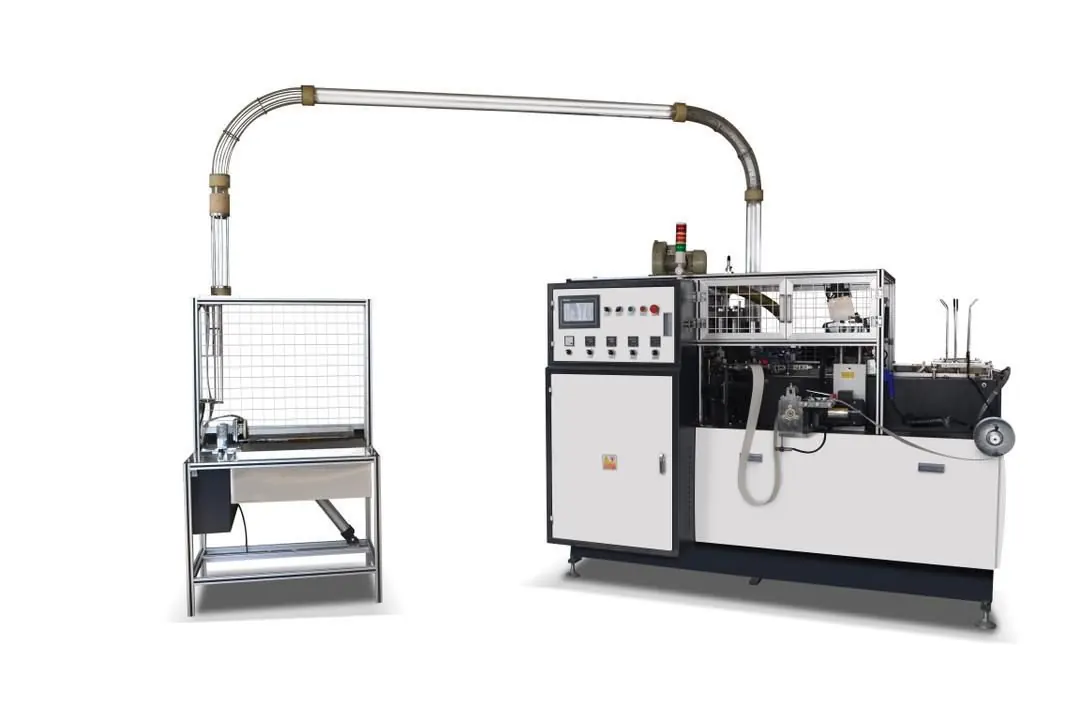
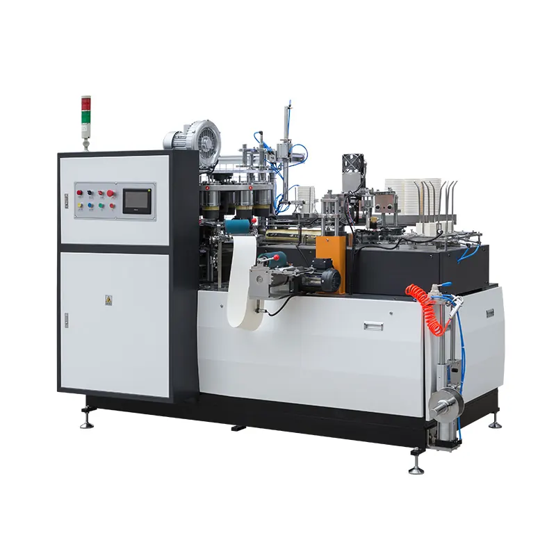
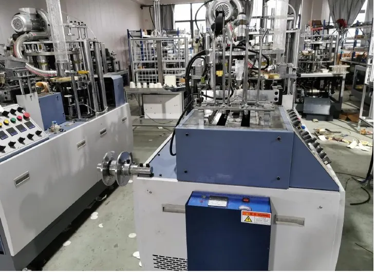
Ask the supplier to assess the geometry and material against the proposed machine configuration. A published cup-size range provides a starting boundary; it does not confirm every shape, board or lid combination inside that range. The HN-M100 product page can support an initial discussion, followed by application-specific confirmation.
Clarify whether the new cup needs only a tooling set or also feeding, forming, collection or other changes. Distinguish required changes from convenient options. Keep the resulting parts list tied to the approved cup drawing.
| Selection input | Why it matters | Evidence to retain |
|---|---|---|
| Top and bottom diameters | Define geometry and taper | Drawing and measurement method |
| Height and capacity definition | Prevent nominal-size ambiguity | Approved dimensional and fill references |
| Rim and lid | Establish the fit requirement | Lid identity and fit-test method |
| Paper and coating | Affect forming and sealing application | Material specification and trial batch |
| Sidewall fan and bottom material | Connect stock to finished geometry | Approved blank and bottom references |
| Tooling and change parts | Define the actual conversion scope | Part list and setup documentation |
Review the fan blank and bottom interface
The cup drawing, sidewall fan and bottom material form one application. A different overlap, blank profile or material condition can affect the finished result even when the machine has the intended mould installed. Ask which references the supplier needs to validate the complete set.
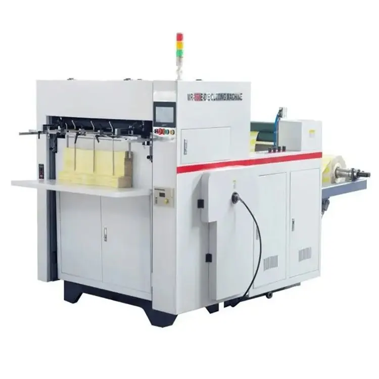
Use the blank die-cutting guide when blanks are sourced or produced separately. Identify who approves the fan drawing and who verifies supplied blanks against it. Avoid treating a generic fan sample as equivalent to the approved production blank.
Plan changeovers as a documented conversion
List every required change part with an identifier and storage location. Request the supplier's changeover instructions and record which settings or checks must be confirmed after conversion. Do not infer a changeover time from the number of moulds alone.
For a factory producing several sizes, plan the order sequence and material availability with the changeover scope. A larger cup range may increase operational complexity even when every size is technically supported. The production-capacity guide explains why those intervals belong in the output plan.
Agree acceptance checks for each application
Check finished dimensions using a repeatable method and agreed conditions. Include rim quality, lid fit where relevant, seam and bottom integrity, stack handling and any packing interface. Do not impose a universal tolerance or force requirement without an approved product specification.
Identify the trial cup, material and tooling in the report. If only one size is demonstrated, record other sizes as untested or supported by separate evidence. Tooling delivery alone does not establish successful production of every listed application.
Control revisions after approval
When the cup drawing, lid or paper changes, ask whether the existing tooling and setup remain suitable. Record the new revision and assessment before combining new stock with old instructions. Keep superseded references clearly separated from current production documents.
Retain an approved cup sample where appropriate, with its identification and storage conditions. Use it as a comparison aid alongside the specification, not as a substitute for defined measurements and acceptance methods.
Frequently asked questions
Can I choose a mould by ounce size alone?
No. Nominal volume does not define the full geometry, rim or material application.
Does a broad machine size range mean no tooling changes?
No. Ask the supplier to identify the moulds and other change parts needed for each cup.
Should the lid be included in the tooling brief?
Yes, when lid fit is a product requirement. Supply the lid identity and agreed fit evaluation method.
Can a paper change affect an existing cup setup?
It can. Review the new material specification and obtain application confirmation rather than assuming geometry alone establishes compatibility.
Prepare a tooling request
Send cup drawings or samples, lid references, material details and your planned size list through the HANNAI inquiry page. Separate initial sizes from future applications so the tooling proposal has a clear scope.